I’m going to shift topics for a while here, from the SD-Access series of blogs to a series of Internet Edge blogs. By Internet Edge, I specifically mean connecting your data center(s) to the Internet.
For those who liked the SD-Access blog series: I have a few more SD-Access blogs fermenting in my brain and hope to be posting them after this series.
Teaser: SD-Access Transit with two data centers and two pairs of fusion firewalls. There are some things to be aware of and design for. This is apparently on Cisco’s radar, but there is no CVD yet, as far as I know.
Ahem, so Internet Edge. More specifically, how you design the Internet connectivity in a data center or two.
This blog will start us on the journey by covering single data center designs as a baseline.
Basic Internet Edge Design (One ISP)
So: what does a basic Internet Edge design look like?
Here’s a diagram as a starting point:
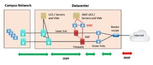 Figure 1: Basic Internet Edge with HA
The diagram shows the “deluxe HA” (High Availability) version of basic Internet Edge. Lots of double devices. Do I hear someone in the back muttering “way too expensive”?
I’m putting this first as an ideal Internet Edge setup (from an HA perspective, anyway).
For now, let’s consider security devices other than a firewall to be independent add-ons that often come with additional complexity. We may get into that topic later in the series.
Also not shown, since it more of a non-Internet Edge security design issue: most sites now have a firewall between users (onsite and remote access) and the servers. In my SD-Access designs, it might be the fusion firewall. This firewall can control ports and, ideally, help stop crypto locker and other malware from spreading from users to servers.
Ok, so what DO I have in the diagram?
On the left is some sort of campus switched/routed network, which may or may not be present at the data center site. For smaller organizations, the data center may be a smallish room or closet in the HQ building along with users. Or it may have gotten moved to a CoLo facility with better physical features, connectivity, and better security, with the HQ connected via 1 or 10 Gbps links.
The campus, in a sense, may include WAN links as well. If you’re doing SD-WAN at a data center site, well, that’s a complication to be discussed in another blog.
Generally, the data center has a couple of “big” switches or a fabric/mesh of smaller spine and leaf switches that connect up the servers. If you’re a Cisco shop, your UCS chassis connect(s) to your Fabric Interconnects, which connect to the data center switching infrastructure. That’s what I intend the tan icon in the above diagram to indicate: all the UCS + FI, TOR switches, etc.
You may have separate servers and switches for the DMZ, as shown or not.
The inner server farm core switches, and the DMZ switches, should connect to different physical or logical interfaces on the firewalls. They, in turn, connect to the Internet border router, possibly / probably via one or two intervening switches.
I added double-headed arrows for routing below the rest of the diagram.
When possible, the simplest thing I know of is to redistribute edge BGP into your internal IGP, OSPF (shown), or EIGRP – your preference. Do that on the border router. Probably OSPF unless you have Cisco firewalls.
For what it’s worth, I consider static routes to be complex, highly NOT simple. (I’m sparing you the whole “static routes are EVIL” rant at this point.) Yes, a small Internet Edge might use them. But if you want dynamic failover at a later date, you’ll have to replace them. My advice is to just “do it right” the first time.
The outer switch may be L2 or L3. If L3, route via your IGP to it. If L2, do the IGP routing through it.
And yes, I would now do routing to the firewall. The code should be mature. And if not, then you need a better firewall vendor. You can route through the firewall, but to my mind, that’s more complicated, needs supporting static routes for peer reachability, etc. And I like being able to “see” devices – Layer 2 devices annoy me; I really do think they’re not best practice.
Side note: I’ve had too many troubleshooting or assessment gigs where after a couple of days resulting in some head-scratching, I had to ask if there was an L2-only device in between points A and B. Every time, I then heard, “oh yeah, I forgot to mention the <whatever>.” Usually, it was the performance/bandwidth chokepoint I was looking for as well. Undocumented invisible or barely visible devices are not your friend when troubleshooting!
For what it’s worth, I also go as far as wishing firewalls were good network citizens doing CDP and/or LLDP. I’ve done too much virtual cable tracing and diagramming – and having to have someone go verify the firewall is connected the way you think it is (by having someone onsite physically tracing the cables) slows troubleshooting down considerably. Any minor extra security exposure from CDP or LLDP seems unlikely to help a hacker much. They probably fingerprinted your firewall anyway.
One ISP, One Router Very Basic Internet Edge
If you operate a smaller / more frugal datacenter, then you probably looked at the above diagram and thought, “that’s my network device salesperson’s dream.”
The reality is that if you have one site and one ISP (getting truly basic), then do you invest in HA pairs of other devices? Maybe yes, maybe not. It can be helpful to limit the number of single points of failure (SPOFs).
Here’s the diagram for a simpler single datacenter / Internet Edge:
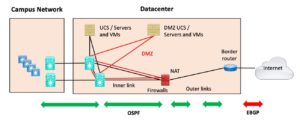 Figure 2: Very Basic Internet Edge
I’ve dropped the outer switch, assuming the firewall and border router may just be directly connected. The DMZ switches are also gone; instead, they are using a different VLAN on the core switches or fabric, shown in red above.
If you want the even more frugal design, you can imagine single-core switches on the campus and a single server core in the data center.
Small and maybe some medium-sized shops may not have separate DMZ server hardware, as shown. So, there might be one UCS or other server chassis, perhaps running VMware, with a DMZ VLAN. Fine, VLANs for the DMZ VMs can connect similarly to what is shown in red in the above diagram. Imagine red lines alongside the black lines extending down from the left UCS server icon in the above diagram.
That is still fairly secure – if a DMZ VM gets hacked, they still would have to hack VMware to get further.
And finally, if a site is being frugal, the routing might be mostly static. Without HA and failover, what’s the value in dynamic routing? Future readiness, perhaps?
Security Note: One of my NetCraftsmen colleagues pointed out that he’s seen major bank networks subjected to ongoing DDOS, where having separate outside hardware really helped mitigate the impact of the DDOS attack. If your DMZ servers are getting pounded, do you want that to also be impacting your non-DMZ servers? If your Internet router to firewall connection runs through the data center core switches, that also might represent additional DDOS exposure. The same might be true for VM’s on common hardware. The conclusion is that virtualized environments that share physical hardware do not isolate this sort of potential exposure.
Two ISPs, One Router
For somewhat additional robustness, you can add a second ISP link to the one router. The logic would be that ISP circuits are exposed to outside influences and, therefore, more likely to fail. Did I mention fiber-seeking backhoes yet?
Here’s the fairly basic (low HA) version of that:
And yes, you’d best run BGP to both ISPs since static routing isn’t going to react automatically to an outage. (Adding tracking and IP SLA or whatever trying to make static routing usually is more complex than just doing dynamic routing!)
Two ISPs, Two Routers
If you’re paying the cost of the second ISP, it probably makes better sense to add a second router as well. That way, your Internet connectivity isn’t dependent on a single router.
Here’s what that looks like:
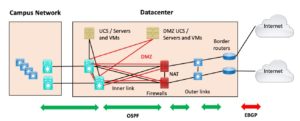 Figure 4: Two ISPs, Two Routers
At this point, you might want to run IBGP between the two border routers. Or just let them advertise 0/0 inwards in the IGP if received via BGP from the attached ISP and do ECMP routing. (Make sure your firewall supports that.)
Routing
The role of OSPF or EIGRP (the IGP, Internal Gateway Protocol) here is to communicate liveness, passing 0/0 default inwards and passing site prefixes out to the border router.
The border router for a single site can just have the ISP using one or more static routes pointing at the single site. I prefer to advertise a summary prefix to the ISP for more dynamic failover, at least when you have two ISPs and/or two border routers. You might as well start out doing that; then you have less rework later if you ever add a second ISP.
This is where it is handy if you own two public /24 blocks. If you don’t, it might be hard (and costly) to obtain them. If you do not have two such blocks, you will have to work with whatever the ISP(s) give you for public address space, and you’ll be somewhat less portable / more locked into them.
You can put a static 0/0 route on the border router pointing outwards. I prefer to receive 0/0 from the ISP. Even with a single ISP, that saves later coordination with the ISP when you wish to add another ISP and become more dynamically routed.
If you’re operating at this basic level, you most likely do NOT need or want a full or partial Internet feed. Have the ISP advertise default to you and call it a day. Avoid swollen Internet routing tables!
For the two ISP / two router routing, we’ll revisit essentially the same topic in the context of two data centers in a later blog in the series. So: more discussion is coming!
Myth buster: (Well, it’s either that or “great grounds for a debate.”) Accepting a full Internet feed does not make you more manly or empowered, and, I’d argue, may not do much for you in terms of external connectivity. Definitely true for Tier 1 ISPs. More debatable if you have Tier 2 or 3 ISPs that might not be as well-connected.
With one ISP, there is no point to a full feed. You’ve got one way out, and the default route (static even) covers that.
With two ISP links, it still seems rather unlikely to help if there is a connectivity issue within your ISP or the peering somewhere. What are the odds a partial or full feed actually helps, making it worth a little more complexity and the cost of the router(s) with greater BGP capacity?
Yes, some people would disagree with this. Strongly, even.
I feel the purpose of two links, with or without two local routers, is to ride out a local outage. If you have one router with two links, you can keep the Internet access going as long as only one of the ISP links goes down. With two routers and two links, you can tolerate losing either link or either router.
Note that a partial feed of the ISP’s prefixes can help if you have two links or better two ISPs and are trying to apply BGP to get approximate outbound load balancing. That’s a topic for a later blog, however, and a different reason for taking the partial feeds.
Conclusion
At this point, we’ve covered several variations on how to connect a single site to the Internet. As we go further in this blog series, we’ll add various complicating factors and some different scenarios. Stay tuned!

