I’ve recently had the pleasure of being involved in some long-term discussions about replacing the building switches and core network for a medium-sized city’s network. That was at the initial budgetary costing exercise stage, which is generally more fun than counting switch ports, POE ports by closet, etc.
We briefly side-tracked onto the topic of how to swap in new building switches, given the structure of the network and the high cost of urban fiber (let alone adding more). The city in question does, in fact, have plans for and ongoing construction of a fiber network it will own, but the switch replacement might start sooner. Then we got back onto the main topic.
How to do the swap-out stayed with me, and an answer soon popped into my head.
Because this might be of more general interest, I’m going to share the idea. That’ll also let those of you with allegedly better ideas brag and tell me about them, deflating my ego. I say “allegedly” since my way is clearly best.
(Joking.)
The idea shown below is not that big an idea, nor is it probably a new idea.
So, all I claim is that the following is one way that can probably be made to work. There may well be other, better, simpler (!) ones. If you know of one, I’d love to hear it.
Background
The existing network uses VLANs heavily. They often span a large portion of the core network.
The current leased fiber network consists of multiple fiber regions. Each of the regions currently consists of a core network of two to say eight buildings plus “dependent” buildings that connect via the core buildings for that region. The regional core networks are rings that include two “headend switches.”
Phrased differently, there are about ten optical rings of switches, having the headend switches in common.
The actual topology within the region is mostly irrelevant for our present purposes.
A diagram might help:
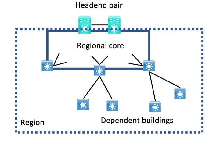
Each region has connection dependencies and some forwarding mechanism dependencies that mean the entire region, including any dependent buildings, would need to be swapped out as a unit. Doing this as “the cutover weekend from hell” is not really feasible.
One major such factor is that most VLANs currently extend back to the headend switch pair, which is where the inter-VLAN routing is located.
Future Design
Possible replacement designs:
- Layer 3 to the access layer network per building design
- Layer 2 to access with Layer 3 up from the building design
- Some form of Cisco SD-Access, probably SD-Access Transit. (That assumes the underlying transport network supports jumbo frames – a detail TBD)
- Some other vendor’s approach
In any of these possible future designs, each regional core is going to be fully L3 for stability and to mitigate spanning-tree instability risks.
The fiber links to the headend are due to be replaced by a routed core network and multiple headends. So, if the uplinks and links between regional core switches are all L3, pre-cabling and then cutting over via shut/, no shut may be simple and quick.
“Presto, you get to those subnets THIS way.”
Problem Statement
There is no extra fiber.
Leasing more fiber (if available) is perhaps possible but costly, and finances are tight. Lead time to get spare fiber might also be high.
So doing a parallel installation followed by shifting access ports isn’t a great option.
For the design reasons stated above (mainly stability), I’m ruling out extended VLANs going forward. I feel that having even one extended VLAN puts all connectivity at risk. If you’ve experienced a spanning-tree loop and what it does to a switched network, you’ll probably agree. (And if not, just don’t go there!)
So trying to be backward compatible for migration and then inserting routing would increase the installation effort (build with L2 then convert to L3?) and make installation more complex.
So how could you build, test, and then incrementally cutover?
The Beauty of Routing
Having a clean per-building addressing scheme (preferably summarizable) and using routing has one really nice aspect. In principle, you can connect the building (or any other “routed chunk”) anywhere upstream, and routing will deliver the packets. (I have to acknowledge you can also do that with trunks and every-VLAN-everywhere, but we want to get away from that.)
One Migration Approach
Pick two new L3 switches per region. They will be the new regional core switches until the corresponding part of the new fiber network is built out. I assume the build-out will be done in phases due to cost and that using it as soon as possible (ASAP) will be desired, also for cost reasons.
For the migration, we will connect the regional core pair to the existing headend switches, which connect to the legacy network, the data centers, etc. As the new network grows, I assume it will be connected back to new headend switches adjacent to the existing ones. And I assume routing from them to the existing headends will be feasible.
We will also connect the new regional core pair to the other regional core switches by trunks. They might be the existing ones, or new ones, based on the new fiber network plans. Using the existing ones is advantageous in the short term for reasons that will shortly be clear.
And we will connect the dependent buildings to the regional core switches.
The key idea is that all the existing uplinks etc., are all VLAN trunks.
I’ve been saying for a while that “VLANs are like patch cables” for some forms of WAN.
So creating more VLANs to use as if they were circuits or fiber pairs is entirely possible. And easy if we work in the near term with the existing cabling. When the new fiber network is put in, each building will be a routed entity, so shifting its uplinks to the new network should be relatively simple.
All the new building and core uplinks will be routed, so we do not need many new VLANs, and they can be local point-to-point only VLANs.
Here’s a diagram showing this:
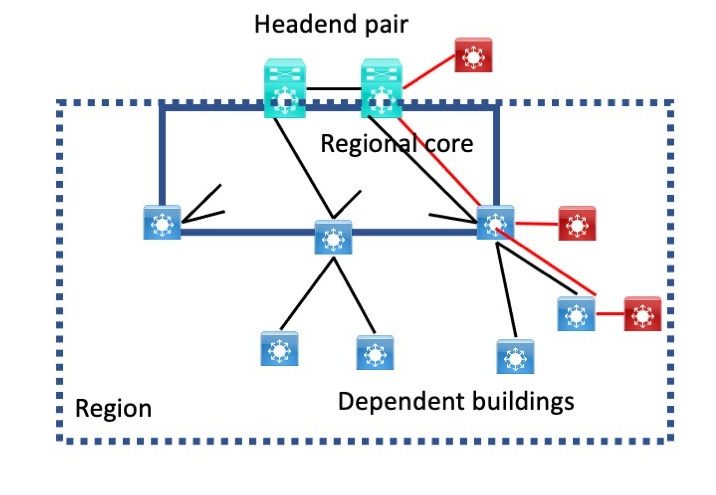
The new L3 switches are shown in red. We connect them to the existing switches, add pt-pt VLANs (“virtual cabling”) as shown with red lines, and use that temporarily for routed links.
Build-out of this probably starts at the top and works outwards. We can use the same trick within buildings if there is insufficient fiber or cabling.
Completing the Migration
Finishing the migration will likely be “bottom-up.” It involves shifting closet switches or replacing them.
We finish dependent buildings, then the region core. At some point, we clean things up.
Note that when we go to actually finish migrating each building’s closets, it will have new access switches and VLANs, new DHCP, etc.
Those are something I do not know how to workaround. For paths to buildings to be routed, each building will need new IP addressing and a DHCP cutover, which can be done one building at a time in the above scheme.
The “usual” DHCP fire drill applies there. Client PCs and phones are rarely a big problem. People tell me that printers running on Windows print servers or using DNS are generally simpler to migrate. Other statically addressed devices may need manual reconfiguration.
Once each building is completed, including routing user traffic over its new uplink VLAN(s), as long as nothing else is using that physical uplink and VLANs, we can move the cabling to the new switches and decommission the old switches involved.
Once all dependent buildings on a core switch have been migrated in that fashion, we might then decommission that core switch. Or we might wait until all are done if trunks pass through that core switch.
I hope the principle here is clear: when you no longer need the old switches and fiber, you can shift the fiber to the new switches and route traffic. If the new fiber is in place, fine; you can shift to that.
Yes, that big picture description omits some details. I see it as flexible, with the key idea being that once you set up a building or region with routed uplinks, you should be able to reconnect it elsewhere, and routing will deliver packets for you.
What about an L3 Network?
The above addressed migrating a wholly L2 network, which I hope is rare.
For L3 links, you can do something similar with routed subinterfaces and VRFs to isolate old from new. Assuming you can’t just replace switches in place for some reason. Perhaps you’re shifting from L2 to access layer to L3 to the access layer, for example.
Conclusions
VLANs and routed dot1q subinterfaces are ways to logically sub-divide a link. If you have a trunk link, adding a new VLAN to connect new devices on each end is one way to connect them without new fiber or circuits.
When you have part of your network where the uplink connectivity is dynamically routed, you can re-attach it elsewhere (physically or logically via VLANs), make sure the routing is still working, and it will just work. Traffic will find that part of the network via the new path.
![]()