I’d like to share a trick I’ve found useful in building a lab to validate configurations. Plus, one other trick that might even be useful in production.
The hope is you might find this useful in building a lab with less equipment. As always, there is a tradeoff: a bit more complexity in your configurations and testing.
Real-world Use Case
I recently worked with an organization that planned to deploy an IOS-XR NCS 540 based network running MPLS, supporting IP multicast, with QoS. One goal was to create and validate configuration templates. The second was to pin down some of the protocol specifics and behaviors, as well as a couple of design details.
We built a lab with 3 x NCS routers as MPLS PE (provider edge) routers, but just one Cat 9300 as CE (customer edge) device. Then used VRFs to make the Cat 9300 act like three different site L3 switches.
We used three NCS routers since we wanted minimal lab artifacts in their configurations, prototype config templates. The Cat 9300 was just going to be doing VRF-Lite, well-known territory, so we could be more flexible with how it was configured.
And yes, we could perhaps have just thrown 3 x Cat9300 in, but the approach used reduced the number of boxes to scrounge, the space required, and a bit of power/cabling.
Here’s the physical diagram:
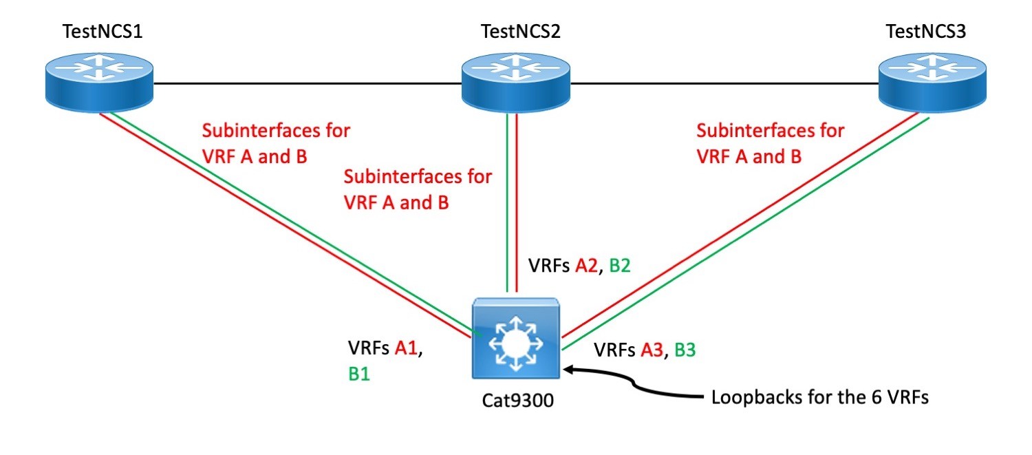
Logically, it is more like the following:
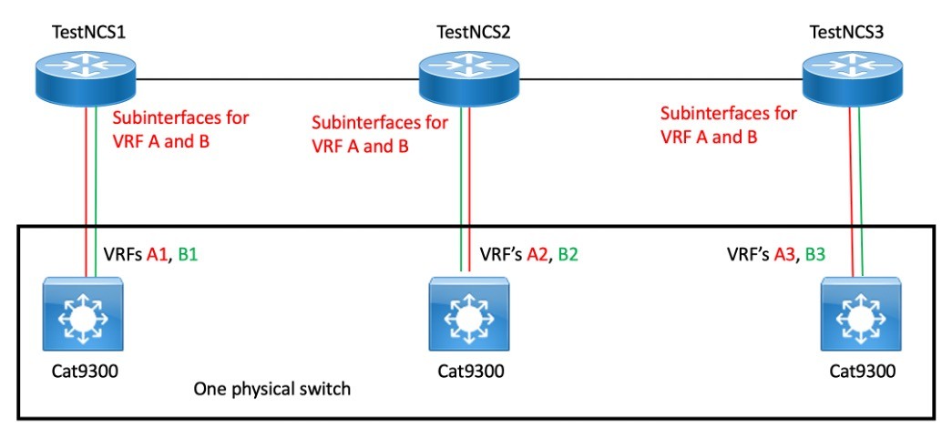
What makes this work is that the VRF name is a local construct. So overall VRFs A and B can be separately routed to the local routing VRFs A1/B1, A2/B2, and A3/B3 based on the connecting interfaces. We think of the latter as A and B, but they simulate A and B VRFs on different chassis, for all purposes.
The working diagram had addresses, BGP ASNs, etc. in it – I removed them as not relevant to this blog.
The idea here was that in production, we’d have VRFs A and B, and likely others. But two was enough for drafting config templates and testing.
On the Cat 9300, we’d normally have VRFs A and B as well. But to mimic 3 different Cat 9300s and their routing tables, we instead have the VRFs A1, A2, A3, and B1, B2, B3.
The main cost of doing this was having to remember to do things like the following:
ping vrf A1 x.x.x.x (where x.x.x.x was an address in VRF A3)
You can think of that as pinging out VRF A on fake switch 1, to hit an address in VRF A on fake switch 3. (Assuming doing it that way is helpful.)
Getting Multicast Into the Act
I’ve found that when under time pressure or late at night (or not so late at night, now that I’ve gotten older), simple troubleshooting is good. Things like checking the routing table are fine. Things like looking at MPLS label bindings and forwarding may be necessary, but they can require more thought and can take time. Not simple, in other words.
Multicast has come up increasingly frequently, especially in a couple of contexts:
- Intercom-like voice application as part of field repair crew comms
- Videos in medical setting, e.g., remote review of ultrasound or other video-like images
When multicast is a key part of the design, how do you do simple? Especially since many people feel that multicast routing / PIM is anything but simple. (And I’ve learned a couple of its surprising behaviors the hard way over the years – prior old blogs.)
The lab trick that I’ve starting using in production is to create a loopback interface and put an IGMP join-group command on it, for a unique per-device multicast group.
What that buys you is the ability to multicast ping the loopback. Which was very useful in the lab depicted above.
In particular, I could use commands like the following to verify functionality or help troubleshoot:
ping vrf A1 224.1.2.3 rep 10000 time 0
That sends 10000 pings to the multicast group shown, which was the IGMP join IPmc group on a loopback in VRF A3. I.e. fake switch 1 sending pings to a multicast destination across the MPLS to fake switch 3s loopback. If things are working, you should get at least some replies back (modulo COPP rate-limiting or CPU impact etc.)
That was quite helpful in getting the MPLS multicast working.
Oh, and thanks Cisco for the challenge created by the documentation omitting a couple of the NCS 540 multicast details and any discussion of configuration options in that regard. Offset by Ryan’s (you know who you are) help!
Where the multicast is critical, one might even continuously send probes to verify ping response. We’re considering doing that for one hospital, as early warning of an IPmc problem.
I have no idea whether ThousandEyes, CatchPoint, Netbeez, and other tools can do multicast ping, although I’d hope they would. The test code in such tools ought not to need modification.
By the way, the multicast ping reply is unicast, which matters if you’re trying to do WireShark or capture packets. Or have ACLs.
Conclusion
The above summarizes a couple of tricks I’ve found helpful in labbing and testing over the years, especially when spare equipment is scarce.
By the way, I do strongly recommend that with the onset of GUI automation tools like DNAC and ACI, having a lab to test “what happens if I do this” can be darn useful! With automation you have a larger “blast radius” (potential human-induced outage scope?) so it is wise to be careful, and test before making changes.
(Especially the “no-brainer” ones – if you don’t apply much thought thinking the change is simple, they’re the ones that can come back and bite you! Also, automation may sometimes do something a bit different than you expect, particularly when it comes to backing out configuration lines to update a configuration.)