This is the second blog in a series of blogs about Cisco’s SD-Access (“SDA”). It will cover device roles and SDA terminology, and some of the high-level choices (how to integrate WLAN, the inter-site transit mechanisms, and how to use DNA Center). This blog is a tour of some of the concepts and terminology in SDA.
Establishing the terminology will set us up to take a more in-depth look at SD-Access in subsequent blogs.
The first blog in the series is What Is SD-Access and Why Do I Care?
Device Roles, Terminology
SD-Access (“SDA”) introduces some new terminology around the switches’ roles in the network. This is a necessary pre-requisite before we can discuss SD-Access.
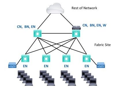
The critical concept in SD-Access is a “fabric site.” A fabric site is a single geographic location or building(s) with an SD-Access VXLAN fabric extending across it. Contrast this to a “fabric domain,” which is a collection of such sites.
Usually, a fabric site will consist of one or more distribution switches and some number of dual-homed access switches – using the prior terminology. We refer to this as a “spine/leaf” topology when it’s in a datacenter.
So far, these blogs have not yet said anything about what’s different about SD-Access from a usage perspective.
A fabric site uses VXLAN tunnels that route over the underlay infrastructure. These allow robust transport of Layer 2 traffic. The result is like having VLANs that exist on every switch in the fabric site, without the stability risks that Layer 2 entails.
Switches in SDA have roles, reflecting what they do within SDA. We still discuss the position of a device in a hierarchical topology as core, distribution, and access. One should generally design a uniform topology along those lines – standardization is the key to simplicity and scalability.
The access switches usually act as “edge nodes (EN’s)” – computers and other devices attach to edge nodes.
In a two-tier topology, the distribution switches generally link to the rest of the network, and so they will probably act as SDA “border nodes (BN’s).” They may also have the edge node role if you plan on connecting central closet devices to them.
The core switches might be the border nodes in a three-tier topology (core/distribution/access). The distribution switches could be underlay-only “intermediate nodes” providing routed connectivity for the access switches. They also act as edge nodes when end systems are plugged into them.
You could also build a network with three layers, core-distribution-access, and even have two or more dedicated border nodes “above” the core switches, with the core switches as intermediate nodes.
An SDA site needs one or more control plane nodes (“control nodes” for brevity). They can be combined border and control nodes or separate devices when necessary for scaling.
Edge nodes learn about the attached devices and register them with the control nodes, which track every end device within the fabric site. Border nodes are the gateway to the rest of the network and the Internet. You can have selected border nodes for the Internet and others connecting to the rest of the organization’s network.
SDA diagrams typically indicate roles by placing letters alongside switch icons. So you might see BN|CN|EN for a combined border, control, and edge node. Or even “BCN.” And “W” gets added for a wireless controller – we’ll come back to that below.
Fabric in a Box or FIAB refers to a single switch performing the BN, CN, and EN roles. FIAB is used for a small site with a single switch present.
You can connect older or less functional switches to the edge nodes. This is intended to support IoT, outdoor, and other such uses. These extended node switches support VLANs and trunks and SGT assignment. The EN provides inter-VLAN traffic enforcement.
Recently policy extended nodes were added: they are switches that can do SGT enforcement, which allows full micro-segmentation. They are especially needed for industrial REP ring topologies.
Note: Cisco’s abbreviations seem to be shifting, with edge nodes becoming “fabric edge” or “FE” to free up “EN” for extended nodes (in an IOT / OT context). You can probably guess what a “PEN” is.
Generally, an organization has DNS, NTP, ISE, DNAC, and other services in a shared services block in one or more data centers.
Wireless Integration Choices
In SDA, wireless AP’s get connected to EN’s. There is a choice as to how they are integrated into SDA.
They can be managed via a WLC in a services block. In this approach, the AP’s reach the WLC via the underlay and global routing table. This is referred to as Over The Top (OTT) design in SDA. This can be convenient in a migration, if you wish to deploy and migrate the LAN side of things and either leave WLAN as is or migrate it later. With OTT, enforcement is done at or near the WLC, either per-SSID or (recently) via SGT assignment at the controller. One drawback is that CAPWAP tunneling consolidates traffic at the WLC, which can become a bottleneck when aggregating traffic from a large number of the new higher-speed AP’s.
If you want local switching, FlexConnect over SDA fabric is not currently supported but may work. It is expected soon in an upcoming release at the time of this writing.
Another choice is to do fabric wireless. The attraction of fabric wireless is that the AP’s act more or less like the edge switches. These switches tunnel traffic into the fabric and assign SGT’s. This means that your wired and wireless users’ traffic follows the same paths through the network and is handled the same as far as segmentation enforcement. They use the same addressing. As a bonus, doing this distributes the AP traffic load among wired switches, with no CAPWAP. Since SDA uses VXLAN tunnels too, in effect extend VLANs across the fabric site, wireless roaming within the site just happens, in effect, with no CAPWAP tunneling. High-speed all the way! Oh, and wired and wireless guest traffic are both handled the same way.
SDA does currently require a WLC at each site (“fabric wireless controller”). This could be a physical WLC. However, depending on scaling requirements, a virtual WLC can now run in an AP at the site, or in one of the switches (combined role or dedicated). The virtual WLC in a switch (“embedded Catalyst 9800 WLC”) is rated as supported 200 AP’s and is more or less a role checkbox in the DNAC GUI. Using an embedded WLC is included in the switch license required for SDA.
Note that a WLC per site does not in itself provide site survivability if the site gets cut off: DNS and ISE are needed.
You can mix OTT and fabric WLC, but there is no roaming between them. Due to this, in a migration, the best practice is to migrate a floor at a time or a building at a time.
Transit Mechanisms
There are three ways of interconnecting fabric sites within an SDA fabric domain:
- IP Transit
- SD-Access Transit
- SD-WAN Transit
We will refer to the network connecting the sites as the “backbone network.”
IP Transit has the site Border Nodes route into the routed backbone network. SDA typically configures BGP and a VRF for each SDA VN (virtual network) on the border nodes. You can then configure matching BGP and VRF’s in the connected backbone network device and across your backbone. (Some call this a “VRF rainbow” because of how it is typically diagrammed.)
Alternatively, you can connect the various fabric VRF’s to the global routing, making the backbone router a fusion router. While this discards segmentation in the backbone, SXP or other means can allow the use of the segmentation for enforcement at datacenter firewalls.
DNAC will configure the BN’s for you (assuming you want BGP), but the rest is up to you.
If you do not already have VRF’s across your backbone network, a fairly substantial amount of configuration would be required to set that up.
Thus, IP Transit is just IP routing between the sites and the rest of the network, with or without preserving VRF’s.
SD-Access Transit (or “SDA Transit” for short) uses LISP to trigger VXLAN tunneling from site BN’s to another site or datacenter BN’s. If you check a box in DNAC, datacenter BN’s become Internet exit points, feeding traffic into fusion firewalls.
SDA Transit provides a VXLAN tunnel overlay interconnecting your fabric sites and preserving the VRF / VN segmentation, all auto-configured via DNAC.
SDA Transit cleanly separates overlay (SDA fabric user/device addresses) from the underlay. The underlay just has to be able to route to the loopback addresses on the switches. Routing between underlay and overlay only takes place on the fusion firewalls or routers.
By way of contrast, IP Transit has to handle all the user addresses and routing as well in the backbone network. That means redistribution at every site border node to backbone network handoff, somewhat more complex, and distributed routing logic. That’s do-able if IP Transit is a better fit for your organization.
SDA Transit requires a large campus or regional setting with adequately low latency. For networks with more latency / greater geographic spread, one of the other transit techniques will be needed.
- Potential advantage: keeps “overlay” addressing/userspace addressing separate from underlay and backbone addressing.
- Potential disadvantage: the fusion firewall aggregates user to datacenter or Internet traffic plus inter-VN traffic, so must support large throughput, making it costly.
- Potential disadvantage: the inter-site tunneling might be viewed as adding complexity.
SD-WAN Transit is the upcoming GUI integration of DNAC and Cisco SD-WAN, details TBD. It could use the same options as IP Transit. “VRF rainbow” from the SD-WAN router to the adjacent SDA fabric BN’s seems likely to be a workable interim solution.
Note that SD-WAN Transit might be useful where an organization has a regional fiber or other high-speed network interconnecting campuses or buildings but needs to also connect small sites with slower / higher-latency connection or field offices across the WAN, etc.
How Can DNA Center Be Used?
For those new to SD-Access, one puzzling factor is where DNA Center fits in. The source of confusion is that DNA Center can be used in several ways.
DNA Center (“DNAC”) is the key GUI component in SD-Access, providing automation and management of large numbers of switches.
There are several ways to use DNAC:
- WLAN AP management – most Cisco AP sites find this quite useful. No SD-Access involved.
- Switch management: track switch inventory, automate switch upgrades, health, and some switch monitoring. Some sites do this. As DNAC has gotten past adding substantial WLAN support, switch features are being added. DNAC can be useful in managing a fleet of LAN switches. It can push out configlets across the fleet as well. No SD-Access involved.
- LAN Automation: automate the deployment of new switches, switch fabrics “underlay” networks using IS-IS routing protocol. Note that you do not have do use LAN Automation for SD-Access, but it can speed greenfield deployments and ensure the correct configuration of all links and routing.
- Full SD-Access overlay deployment and management: this is typically done after LAN automation deploys the “underlay” but can also be done over any existing “brownfield” L3 to the access layer deployment. DNA Center is mandatory for this.
Even if you have a brownfield existing network, you may want to do LAN Automation for consistency with later new deployments that do use LAN Automation.
References
Cisco Press book, Software Defined Access