
OSPF is a protocol loaded with a myriad of details and a lot of unique behaviors. These always need to be considered at length when designing a solution but CCIE/JNCIE candidates especially need to be very cognizant of these when configuring for a lab scenario or solving a trouble ticket. Ignoring or not being mindful of the smallest protocol details may mean losing points for the entire question or worse still, points for multiple dependent questions.
This blog post, at the surface, discusses a unique behavior that is seen in OSPF networks. But the overall objective of the blog post is intended to be greater. If this object is stated succinctly, it would be:
- Always use the proper verification methods to ascertain successful configuration of a scenario.
All too often, candidates struggle not just with the configuration of a scenario but also with the methods that are best suited to test their configuration’s validity. Subconsciously for a candidate, the ever present thought should be : “What method can/will the proctor/script use to verify and award points for this question”? That aspect, the verification/testing methods, needs be the sharpest, most polished and most used weapon in the arsenal of a CCIE/JNCIE candidate. After all, if one cannot verify their own work properly, how would they know if they “nailed” the question or “bungled” it?
For this post, the following topology will be used.
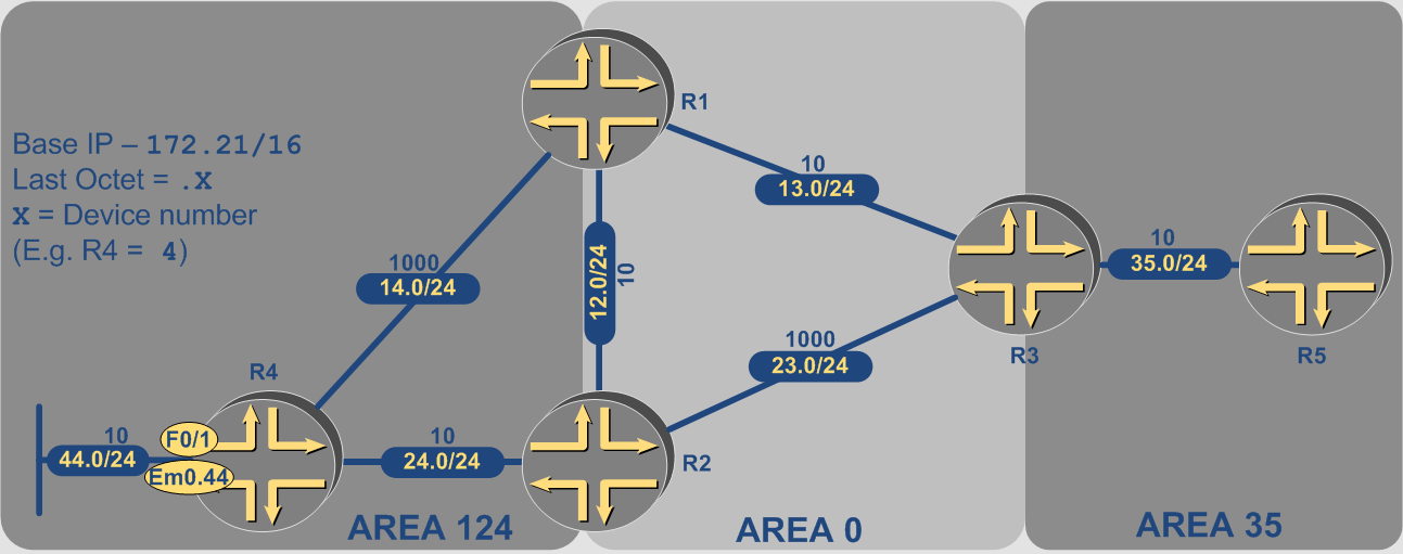
The central idea is for R4 to inject a route in the topology that R5 should be able to reach. There are two main objectives for this post:
- Understand the actual installation of the R4’s prefix via OSPF in R5’s RIB
- Understand the path of an actual IP packet from R5 to the destination at R4
The configuration/verification will occur on IOS/Junos simultaneously. As for the initial configurations, all OSPF neighborships have been verified to be UP in proper areas as indicated on the topology. The respective OSPF costs (metrics) displayed on the topology for each link have also been hard-coded via CLI on both IOS and Junos. The route 172.21.44.0/24 (Ethernet port on R4) has not yet been advertised, by any means at all, into OSPF.
Advertising the Prefix in LSA 1
The easiest and most straighforward way for R4 to advertise the prefix is by including it in its Router LSA (Type 1). To facilitate this, the following configuration is added to IOS and Junos respectively
IOS
interface fastethernet0/1
 ip ospf 1 area 124
Junos
protocols {
    ospf {
        area 0.0.0.124 {
            interface em0.44;
        }
    }
}
The result is the inclusion of the 44.0 network as a stub network (Type 3) in R4’s LSA 1
IOS
R4#show ip ospf database router self-originate
            OSPF Router with ID (172.21.14.4) (Process ID 1)
                Router Link States (Area 124)
  LS age: 4
  Options: (No TOS-capability, DC)
  LS Type: Router Links
  Link State ID: 172.21.14.4
  Advertising Router: 172.21.14.4
  LS Seq Number: 80000006
  Checksum: 0x888E
  Length: 60
  Number of Links: 3
    Link connected to: a Stub Network
     (Link ID) Network/subnet number: 172.21.44.0
     (Link Data) Network Mask: 255.255.255.0
      Number of TOS metrics: 0
       TOS 0 Metrics: 10
    Link connected to: a Transit Network
     (Link ID) Designated Router address: 172.21.24.4
     (Link Data) Router Interface address: 172.21.24.4
      Number of TOS metrics: 0
       TOS 0 Metrics: 10
    Link connected to: a Transit Network
     (Link ID) Designated Router address: 172.21.14.4
     (Link Data) Router Interface address: 172.21.14.4
      Number of TOS metrics: 0
       TOS 0 Metrics: 1000
Junos
nbhasin@R4# run show ospf database advertising-router self router detail
    OSPF database, Area 0.0.0.124
 Type       ID               Adv Rtr           Seq      Age  Opt  Cksum  Len
Router  *172.21.14.4      172.21.14.4      0x80000005  2370  0x22 0xed2d  60
  bits 0x0, link count 3
  id 172.21.14.1, data 172.21.14.4, Type Transit (2)
    Topology count: 0, Default metric: 1000
  id 172.21.24.4, data 172.21.24.4, Type Transit (2)
    Topology count: 0, Default metric: 10
  id 172.21.44.0, data 255.255.255.0, Type Stub (3)
    Topology count: 0, Default metric: 10
  Topology default (ID 0)
    Type: Transit, Node ID: 172.21.24.4
      Metric: 10, Bidirectional
    Type: Transit, Node ID: 172.21.14.1
      Metric: 1000, Bidirectional
LSA 1 to LSA 3 Conversion
This LSA 1, as per OSPF specification, will be flooded inside Area 124. R1 and R2 are ABRs for Area 124. They will in turn run their respective SPF algorithms on the Link State Database (LSDB) of Area 124 and the results will be flooded into Area 0 using separate Summary LSAs (LSA 3) for each internal Area 124 route (this statement is of course oversimplified but the full explanation is beyond the scope of this blog post). These LSA 3 are received by R3 as a result of the flooding. Appropriately, the prefix 172.21.44/24 is advertised in two separate LSA 3 as well, one generated by each ABR.
IOS
R3#show ip os database summary 172.21.44.0
            OSPF Router with ID (172.21.13.3) (Process ID 1)
                Summary Net Link States (Area 0)
  LS age: 381
  Options: (No TOS-capability, DC, Upward)
  LS Type: Summary Links(Network)
  Link State ID: 172.21.44.0 (summary Network Number)
  Advertising Router: 172.21.12.1
  LS Seq Number: 80000002
  Checksum: 0x6326
  Length: 28
  Network Mask: /24
        TOS: 0  Metric: 1010
  Routing Bit Set on this LSA
  LS age: 192
  Options: (No TOS-capability, DC, Upward)
  LS Type: Summary Links(Network)
  Link State ID: 172.21.44.0 (summary Network Number)
  Advertising Router: 172.21.12.2
  LS Seq Number: 80000002
  Checksum: 0x3D23
  Length: 28
  Network Mask: /24
        TOS: 0  Metric: 20
Junos
nbhasin@R3# run show ospf database area 0 lsa-id 172.21.44.0 detail
    OSPF database, Area 0.0.0.0
 Type       ID               Adv Rtr           Seq      Age  Opt  Cksum  Len
Summary  172.21.44.0      172.21.12.1      0x80000003   512  0x22 0x6127  28
  mask 255.255.255.0
  Topology default (ID 0) -> Metric: 1010
Summary  172.21.44.0      172.21.12.2      0x80000003    11  0x22 0x8bdd  28
  mask 255.255.255.0
  Topology default (ID 0) -> Metric: 20
LSA 3 Selection and Installation in RIB
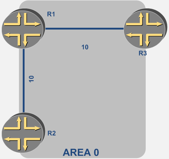
Now, the installation of routes via LSA 3 in OSPF is not purely SPF based. In essence, it has Link State behavior combined with Distance Vector behavior. Essentially, any OSPF router will run the SPF algorithm on the LSDB of the area to create the SPF tree with the calculating router as the root. Any aspiring CCIE/JNCIE should be able to create this tree with any router at the root, given enough information. In R3’s case, this tree for Area 0 will be as follows.
But this is where the Link State behavior ends. For LSA 3 installation, the calculating router will simply take an LSA 3 advertised by an ABR and calculate the metric of the prefix that LSA contains as if the route advertised was directly attached to the ABR – essentially like a stub route in LSA 1. Thus, from R3’s point of view, the 172.21.44/24 network is reachable as follows:
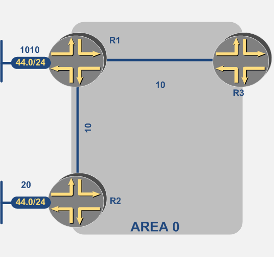
Thus, for R3, the choice is simple and the route that is installed in the one via R2.
IOS
R3#show ip route 172.21.44.0
Routing entry for 172.21.44.0/24
  Known via "ospf 1", distance 110, metric 40, type inter area
  Last update from 172.21.13.1 on FastEthernet0/0.13, 01:02:13 ago
  Routing Descriptor Blocks:
  * 172.21.13.1, from 172.31.12.2, 01:02:13 ago, via FastEthernet0/0.13
      Route metric is 40, traffic share count is 1
Junos
nbhasin@R3# run show route 172.21.44 detail
inet.0: 11 destinations, 11 routes (11 active, 0 holddown, 0 hidden)
172.21.44.0/24 (1 entry, 1 announced)
        *OSPF   Preference: 10
                Next hop type: Router, Next hop index: 557
                Address: 0x9334298
                Next-hop reference count: 8
                Next hop: 172.21.13.1 via em0.13, selected
                State:
                Age: 1:45:21    Metric: 40
                Area: 0.0.0.0
                Task: OSPF
                Announcement bits (1): 0-KRT
                AS path: I
[edit]
nbhasin@R3# run show ospf route 172.21.44.0/24 extensive
Topology default Route Table:
Prefix             Path  Route      NH       Metric NextHop       Nexthop
                   Type  Type       Type            Interface     Address/LSP
172.21.44.0/24     Inter Network    IP           40 em0.13        172.21.13.1
  area 0.0.0.0, origin 172.21.12.2, priority medium
LSA 3 to LSA 3 Conversion
The last part of this process, namely the route installation at R5 will follow the same principles as discussed for R3. R5 will compute the SPF tree for Area 35. In this simplistic topology, that tree will have one edge and two vertices, R3 and R5. R3 then essentially becomes R5’s gateway out of the Area. A more important question that should be asked, and really the CCIE/JNCIE candidate should be well aware of is R3’s re-advertisement of Summary LSAs from Area 0 to Area 35. This behavior again is dictated by Distance Vector not Link State principles. Namely, R3 will only advertise Inter Area routes that it deemed best and furthermore, installed in its own RIB. Any LSA 3 routes that were either not installed in the RIB because of metric reasons or due to filtering will not be re-advertised into another area. Therefore, R5 only receives a single LSA 3 describing 172.21.44/24.
IOS
R5#show ip ospf database | begin Summary
                Summary Net Link States (Area 35)
Link ID         ADV Router      Age         Seq#       Checksum
172.21.12.0     172.21.13.3     1695        0x80000003 0x00DFA7
172.21.13.0     172.21.13.3     1695        0x80000003 0x007020
172.21.14.0     172.21.13.3     1452        0x80000003 0x00990A
172.21.23.0     172.21.13.3     1695        0x80000003 0x00D1D2
172.21.24.0     172.21.13.3     1452        0x80000004 0x00BDB2
172.21.44.0     172.21.13.3     954         0x80000003 0x00470C
R5#
R5#show ip ospf database summary 172.21.44.0
            OSPF Router with ID (172.21.35.5) (Process ID 1)
                Summary Net Link States (Area 35)
  Routing Bit Set on this LSA
  LS age: 984
  Options: (No TOS-capability, DC, Upward)
  LS Type: Summary Links(Network)
  Link State ID: 172.21.44.0 (summary Network Number)
  Advertising Router: 172.21.13.3
  LS Seq Number: 80000003
  Checksum: 0x470C
  Length: 28
  Network Mask: /24
        TOS: 0  Metric: 40
Junos
nbhasin@R5# run show ospf database netsummary lsa-id 172.21.44.0
    OSPF database, Area 0.0.0.35
 Type       ID               Adv Rtr           Seq      Age  Opt  Cksum  Len
Summary  172.21.44.0      172.21.13.3      0x80000003  2732  0x22 0x470c  28
[edit]
nbhasin@R5# show ospf database netsummary lsa-id 172.21.44.0 extensive
    OSPF database, Area 0.0.0.35
 Type       ID               Adv Rtr           Seq      Age  Opt  Cksum  Len
Summary  172.21.44.0      172.21.13.3      0x80000003  2737  0x22 0x470c  28
  mask 255.255.255.0
  Topology default (ID 0) -> Metric: 40
  Aging timer 00:14:23
  Installed 00:45:34 ago, expires in 00:14:23
  Last changed 01:57:36 ago, Change count: 1
So, having only a single LSA describing the network, R5 does not really have a decision to make and installs the LSA as an Inter-Area route into the RIB. Once again, the total metric for the route is (LSA_Metric)+(Metric_to_the_ABR).
IOS
R5#show ip route 172.21.44.0
Routing entry for 172.21.44.0/24
  Known via "ospf 1", distance 110, metric 50, type inter area
  Last update from 172.21.35.3 on FastEthernet0/0, 01:40:25 ago
  Routing Descriptor Blocks:
  * 172.21.35.3, from 172.21.13.3, 01:40:25 ago, via FastEthernet0/0
      Route metric is 50, traffic share count is 1
Junos
nbhasin@R5# run show route 172.21.44 detail
inet.0: 9 destinations, 9 routes (9 active, 0 holddown, 0 hidden)
172.21.44.0/24 (1 entry, 1 announced)
        *OSPF   Preference: 10
                Next hop type: Router, Next hop index: 549
                Address: 0x9334208
                Next-hop reference count: 12
                Next hop: 172.21.35.3 via em0.35, selected
                State:
                Age: 2:16:10    Metric: 50
                Area: 0.0.0.35
                Task: OSPF
                Announcement bits (1): 0-KRT
                AS path: I
[edit]
nbhasin@R5# run show ospf route 172.21.44.0/24 extensive
Topology default Route Table:
Prefix             Path  Route      NH       Metric NextHop       Nexthop
                   Type  Type       Type            Interface     Address/LSP
172.21.44.0/24     Inter Network    IP           50 em0.35        172.21.35.3
  area 0.0.0.35, origin 172.21.13.3, priority medium
The Resulting IP Data Plane
So, it can be said with relative certainty that R5 is installing the LSA 3 that was injected by R3 to describe the LSA 3 that was injected by R2.
This is where one must go back to the theme of testing everything properly and in its entirety.
Suppose the CCIE/JNCIE task mandated that “for that traffic from R5 to R4, R2 must be preferred over R1 to provide gateway services”. If one was just looking at routing tables to verify the configuration, they may prematurely, and ultimately wrongly in this case, congratulate themselves and chalk up 3 points for the home team. In reality, they have just scored a 0.
An astute CCIE/JNCIE student would always be aware of the fact that if traffic is travelling from one area to another, then each ABR traversed can affect the routing of the packet, regardless of the original intent of the sender as per the RIB/LSDB. In this particular case, it can be argued the the orignal intent of R5 was to send the packet via R3 and then R2. But since IP routing really takes place hop-by-hop with each hop making an independent decision, one has to be mindful of at least the important hops along the way. One such hop is R1. It is deemed important as it is also an ABR between Area 0 and 124. A packet that is sent from R5 to R4 will eventually end up at R1, its routing completely dependent on the routing table of R1. And how is R1 routing to 172.21.44/24?
IOS
R1#show ip route 172.21.44.0
Routing entry for 172.21.44.0/24
  Known via "ospf 1", distance 110, metric 1010, type intra area
  Last update from 172.21.14.4 on FastEthernet0/1.14, 01:58:46 ago
  Routing Descriptor Blocks:
  * 172.21.14.4, from 172.21.14.4, 01:58:46 ago, via FastEthernet0/1.14
      Route metric is 1010, traffic share count is 1
Junos
nbhasin@R1# run show route 172.21.44 extensive
inet.0: 11 destinations, 11 routes (11 active, 0 holddown, 0 hidden)
172.21.44.0/24 (1 entry, 1 announced)
TSI:
KRT in-kernel 172.21.44.0/24 -> {172.21.14.4}
        *OSPF   Preference: 10
                Next hop type: Router, Next hop index: 557
                Address: 0x9334178
                Next-hop reference count: 4
                Next hop: 172.21.14.4 via em0.14, selected
                State:
                Age: 2:44:30    Metric: 1010
                Area: 0.0.0.124
                Task: OSPF
                Announcement bits (1): 0-KRT
                AS path: I
[edit]
nbhasin@R1# run show ospf route 172.21.44.0/24 extensive
Topology default Route Table:
Prefix             Path  Route      NH       Metric NextHop       Nexthop
                   Type  Type       Type            Interface     Address/LSP
172.21.44.0/24     Intra Network    IP         1010 em0.14        172.21.14.4
  area 0.0.0.124, origin 172.21.14.4, priority medium
So, R1 is routing this traffic directly to R4 via an interface with an abysmally high metric. But if LSA 3 is flooded throughout an area, then just like R3, should not R1 have an LSA 3 from R2 with a metric of 20?
IOS
R1#show ip ospf database summary 172.21.44.0 adv-router 172.21.12.2
            OSPF Router with ID (172.21.12.1) (Process ID 1)
                Summary Net Link States (Area 0)
  LS age: 29
  Options: (No TOS-capability, DC, Upward)
  LS Type: Summary Links(Network)
  Link State ID: 172.21.44.0 (summary Network Number)
  Advertising Router: 172.21.12.2
  LS Seq Number: 80000001
  Checksum: 0x8FDB
  Length: 28
  Network Mask: /24
        TOS: 0  Metric: 20
Junos
nbhasin@R1> show ospf database lsa-id 172.21.44.0 advertising-router 172.21.12.2 extensive
    OSPF database, Area 0.0.0.0
 Type       ID               Adv Rtr           Seq      Age  Opt  Cksum  Len
Summary  172.21.44.0      172.21.12.2      0x80000004  2588  0x22 0x89de  28
  mask 255.255.255.0
  Topology default (ID 0) -> Metric: 20
  Aging timer 00:16:52
  Installed 00:43:05 ago, expires in 00:16:52, sent 00:43:03 ago
  Last changed 02:52:00 ago, Change count: 1
Every well-prepared CCIE/JNCIE candidate should be smiling now as they should know the reason for this behavior. It lies in the OSPF route selection process. OSPF always prefers Internal routes over Inter-Area routes over External routes no matter what the metric. So even though there is an LSA 3 with a metric of 20, R1 still installs the route out of the information in LSA 1 flooded by R4 inside Area 124. The traceroute performed at R5 will further illustrate the obvious.
IOS
R5#traceroute 172.21.44.4
Type escape sequence to abort.
Tracing the route to 172.21.44.4
  1 172.21.35.3 12 msec 32 msec 12 msec
  2 172.21.13.1 20 msec 44 msec 20 msec
  3 172.21.14.4 64 msec *  56 msec
Junos
nbhasin@R5# run traceroute 172.21.44.4
traceroute to 172.21.44.4 (172.21.44.4), 30 hops max, 40 byte packets
 1  172.21.35.3 (172.21.35.3)  0.265 ms  0.242 ms  0.138 ms
 2  172.21.13.1 (172.21.13.1)  0.711 ms  0.393 ms  0.369 ms
 3  172.21.44.4 (172.21.44.4)  0.528 ms  0.506 ms  0.473 ms
This is essentially the discordance between the OSPF’s control plane and the data plane the IP packet is forwarded on. Thus, the IP RIB on the source router is a very weak verification tool at best when the question is clearly (one can argue ambiguously) asking for the configuration to affect the IP data plane. Usually, with enough practice, a CCIE/JNCIE candidate can see the pitfalls in such a seemingly innocuous scenario from far away, intuitively realizing that there are problems present underneath the seemingly calm surface.
Possible Solutions
One last item is the issue of actually solving the question. Depending on the conditions binding the candidate’s configuration option, these could be varied. Just redistributing the connected route to bring it into the topology as an LSA 5 will also not work in this case. The routers determine the next-hop for the external route using the ASBR’s router-id. Unfortunately, R4’s router-id, whatever it may be, will always be matched by R1 to an LSA 1 flooded by R4 and the next-hop once again will be directly connected interface to R4.
A typical CCIE solution would be to use a virtual-link or a GRE tunnel, once again based on the boundaries set by the exam, and introduce the route from R4 into Area 0 or another area different from Area 124. Then R1 will be allowed to create an SPF tree to R4 (or use R2 as a proper ABR in the second case), via R2 and install the route via R2. The actual configuration for this is left to the reader to perform.
Recommended Resources
The following resources are recommended, especially for the CCIE/JNCIE candidates:
- RFC 2328
- Anatomy of an Internet Routing Protocol by John T. Moy – ISBN – 978-0201634723
- Routing TCP/IP, Volume 1 by Jeff Doyle and Jennifer Carroll – ISBN – 978-1587052026