
I’ve been seeing folks trying to use Cisco Nexus VPC port-channels, and it seems useful to blog about How VPC Works. Part of my goal here is to follow this with a blog about designing to mix Layer 2 (L2) VPC port-channels with Layer 3 (L3) routing, which definitely requires knowing what you’re doing (it’s not necessarily all that hard, you just have to be clear about where your routing peers are).
Basic VPC 101
Ok, so let’s get started on our “review” of VPC. Please refer to the diagram below as we discuss this
.
Virtual Port Channel (VPC) ties two Nexus 7K or 5K switches together by doing a great job of spoofing Layer 2 (L2), including STP BPDU (Spanning Tree hellos) and FHRP (First Hop Routing Protocol — HSRP, VRRP, GLBP) behavior. At L2, the switches behave like one switch, while retaining their distinct identities, unlike the Cisco VSS technique used with the 6500 switches.
For VPC, you would likely connect the two switches together by 10 G links, preferably one on each of two different line cards for robustness, and declaring that link to be a port-channel and a VPC peer-link. It is a special link for carrying L2 traffic between the VPC peer switches when there is a link failure. Normally it should get little use. Before the peer link will come up, you also have to set up VPC keepalives to detect dual active peers when the VPC peer link is down. That is a situation where you might get duplicate packets or have other problems, so being able to detect it and react appropriately is important.There are other steps to configuring VPC, but let’s keep this as simple as possible for now.
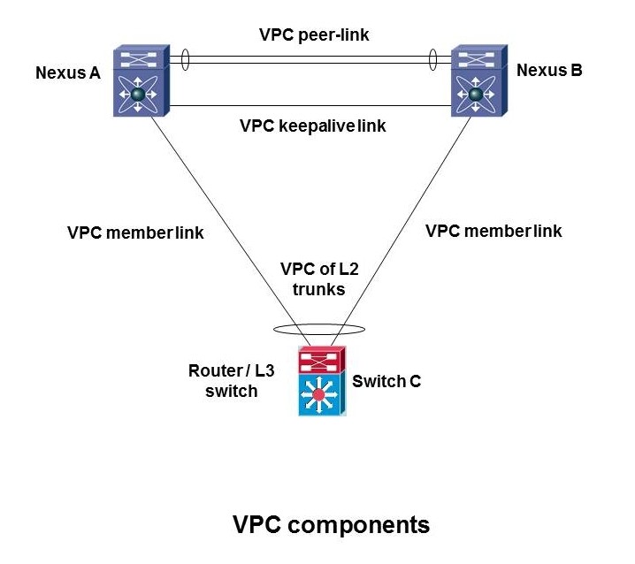
Once the VPC pair is set up (configured), you can then start adding multi-chassis port-channels that connect to the VPC pair. In terms of the diagram below, you can add the port-channel to switch C. When you connect up another device, and tell it two or more links are in a port-channel, and they’re spread across the two VPC peers, that’s a VPC port-channel. The links that make it up are referred to as member links.
When setting up member links, you do have to configure the VPC peer end of things as well. Both ends of the member links have to be configured for port-channel. The VPC switch ends get a special “vpc number” command as well. Switch C thinks it has a normal port-channel — no extra commands needed.
The following diagram illustrates some of these terms.
 If you are doing routing on the VPC peers, the keepalive link might also be a point to point routed link, probably N x 10 Gbps. If the switches are Layer 2 only, then the management ports might be used for the keepalive link. It need not be a 10 Gbps link in that case.
Now we need to take a look at how L2 frame forwarding works with VPC.
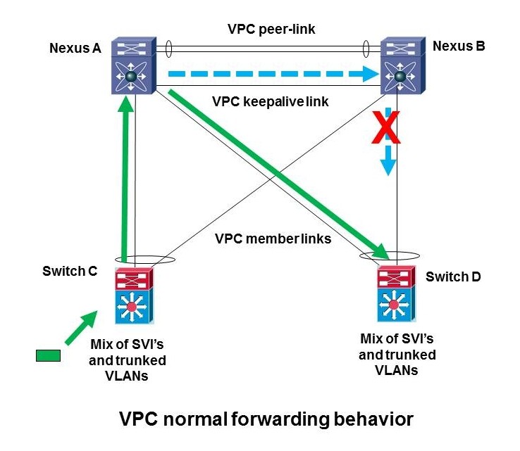
There’s one big rule in VPC, illustrated below. This rule represents how Cisco coded it, with the intent being to prevent bridge forwarding looping and duplicate packets, to make Layer 2 work correctly without needing Spanning Tree Protocol (STP) to do so.
 Here’s the rule. Say the green packet (bottom left) reaches the left bottom switch C. If it is forwarded (based on hashing) up the left VPC port-channel member link, Nexus A is expected to forward it out any member link that the switching table says to use. So the normal expectation is when A receives a frame, it forwards it, for example to D. This is shown by the diagonal green arrow above. If for some reason the frame is sent across the VPC peer link (blue dotted line) to Nexus B, B is not allowed to forward the frame out a member link (say to D), because that might cause looping or duplicate packets.
Now please refer to the figure below.
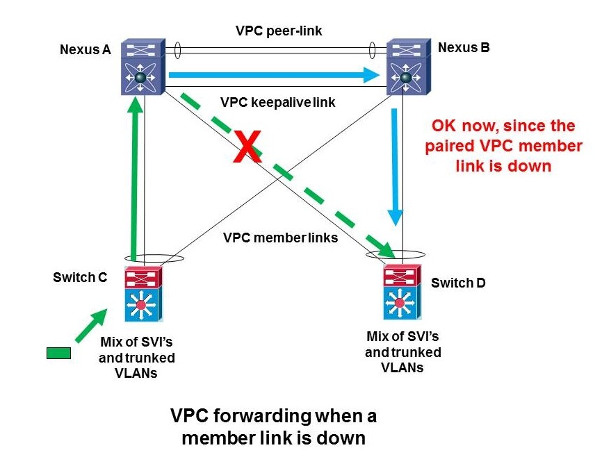
The one exception to that behavior is what happens if the member link from A to D, the one with the green diagonal arrow next to it, goes down (as shown by the red X). In that case and only in that case is Nexus B allowed to forward a frame that came across the member link. B can forward a frame that came across the peer link out the right B to D link because the diagonal link going to that switch — the paired VPC A to D member link — is down. Or in other words, VPC can use the blue path because the dashed A to D green link is down.

Restatement of VPC Rule 101
To put it another way, VPC peers are expected to forward a frame received on a member link out any other member link that needs to be used. Only if they cannot do so due to a link failure, is forwarding across the VPC peer link and then out a member link allowed, and even then, the cross-peer-link traffic can only go out the member link that is paired with the member link that is down.
What you might not expect at this point is that the same rules apply to routed traffic. And that since VPC does no spoofing of the two peers being one L3 device, packetes can get black-holed.
Summary
You’ve got to know the rules to understand basic and more complex VPC behavior, and how to design for it. I’ve tried to state the rules in a simple way above.
By the way, should the peer link fail, the keepalives detect that, and the secondary VPC peer shuts down all VPC member ports to avoid STP loops. MAC address or a configured priority (good idea) are used to determine the primary and secondary VPC peers.
References
Cisco NX-OS Virtual PortChannel: Fundamental Design Concepts …
Pete, this is all very clear.
I do have a question, though. While I realize there are benefits to having them as two separate physical links, can the VPC keepalives be sent across the VPC peer link?
Never mind my earlier question (if I actually submitted it). I was wondering if the keepalive link could be combined with the peer link. I forgot the keepalive link can be done over the management port.
I ok’d posting these, since others may have the same question. You always want keepalives on a different link than the VPC peer link, since their purpose is to detect a situation with the peer still up but VPC peer link down. You just can’t do that if they’re running over the peer link. Instead, you can use the management port. Or, if you put a separate point-to-point routed link between the peers, in parallel with the VPC peer-link, you can use that for the keepalives.
BTW, if the keepalive link fails, the VPC will keep working (but might not come up if there is a failure). If the VPC fails, you might have some problems with duplicate packets or looping, since both the primary and secondary peers will not know the other is still up, and both might be forwarding frames.
Hi, I am beginning learning about this topic and it is very easy the way you explain it. I have learned more about the traffic path. Thanks!!
Glad I managed to make it simple! I try, sometimes the words just keep multiplying on me!