Introduction
We’ve been talking about IP Multicast. This month I’m going to start covering PIM Sparse Mode. Previous articles that might be of interest:
Sparse Versus Dense Mode
Recall that PIM Dense Mode is used (in principle) when the multicast is desired in most locations. Thus initial multicast packets are flooded everywhere, with pruning cutting off traffic to locations that do not need the multicast feed. Until recently, PIM Dense Mode suffered from periodic re-flooding every 3 minutes, but in 12.1(5)T, the PIM Dense Mode State Refresh feature alleviated this. With this feature, PIM Dense Mode is arguably suitable for simple implementation of multicast. Especially where the additional control of PIM Sparse Mode is not needed, and where occasional “accidental” flooding would not be very harmful.
PIM Sparse Mode uses an explicit request approach, where a router has to ask for the multicast feed with a PIM Join message. PIM Sparse Mode is indicated when you need more precise control, especially when you have large volumes of IP multicast traffic compared to your bandwidth. PIM Sparse Mode scales rather well, because packets only go where they are needed, and because it creates state in routers only as needed. Because of this, it has been written up as an Internet Experimental Protocol.
The price we pay for this extra control is mild extra complexity. PIM Sparse Mode uses a special router called a Rendezvous Point (RP) to connect the flow source or multicast tree to the router next to the wannabe receiver. The RP is typically used only temporarily, as we’ll see below.
There can be different RP’s for different multicast groups, which is one way to spread the load. There is usually one RP per multicast group. Redundancy of RP’s is an advanced topic, and requires a little deeper expertise. One way to do this is with the MSDP protocol (possible later article in the series).
Recall that a PIM Join message is sent towards a Source (or for PIM-SM, possibly towards an RP), based on unicast routing. The Join message says in effect “we need a copy of the multicasts over here”. It connects the sender of the Join and intervening routers to any existing multicast tree, all the way back to the target of the Join if necessary. A Prune message says in effect “we no longer need this over here”. A router receiving a Prune sees whether it has any other interfaces requiring the multicast flow, and if not, sends its own Prune message. One advanced technique is to arrange a separate and perhaps different copy of the unicast routing information just for multicast purposes. This allows “steering” of the Join messages. MultiProtocol BGP, MBGP, for multicast, is one way to do this (possible later article in the series).
Basic Rendezvous Point (RP)
We’ve seen so far that PIM-SM uses a Rendezvous Point (RP), to connect source and receivers. There can be only one RP per multicast group, and the simplest implementation uses one RP for all the multicast groups.
Let’s talk through the basics of how the RP is used. Let’s assume the source starts sending before there any receivers. If things happen the other way around, some of the details change slightly, but it’s not very different.
So: the multicast source starts sending. As we’ve already noted, there is no protocol or anything for registering sources with IP multicast. The source sends and it is up to the neighboring router(s) to do the right thing. With PIM-SM, the neighboring router knows about the RP. (How it knows is a topic for a whole separate article.) The neighboring router forwards the multicast data to the RP by encapsulating it in a unicast Register message or messages. Normal routing delivers the Register to the RP. The RP de-encapsulates the multicast and forwards copies down any Shared Tree (there is one pre-built if there were receivers Joined up before the Source started sending). If there are receivers (Shared Tree state outbound interfaces), the RP sends a PIM Join back towards the Source. This connects the Source to the RP with a Source Tree, the (S, G) Shortest Path Tree (SPT). Once the RP receives multicasts along this SPT, it sends a Register-Stop to tell the router by the Source to stop sending Register packets. The reason for this behavior is that no multicast packets are lost, if there are receivers already present.
By the way, if there are no receivers present, the Register-Stop message is sent. Then when a receiver subsequently shows up (IGMP to neighbor router, PIM Join from neighbor router back to RP), then the RP sends the PIM Join to the Source at that time.
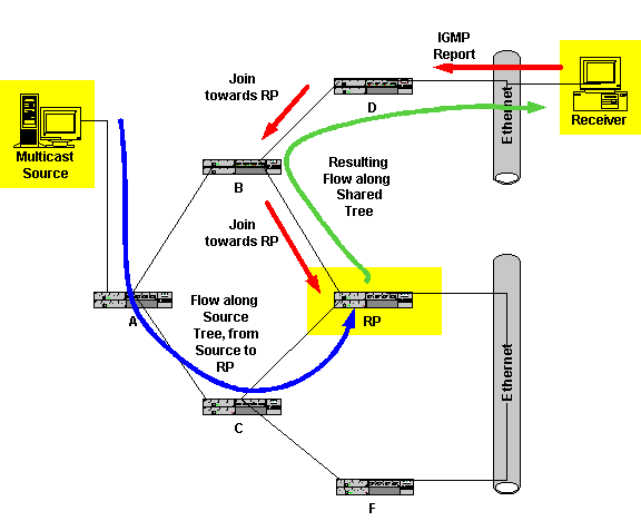
The following figure assumes there is a source and active receivers (not shown). The shown receiver sends a IGMP Report to router D. Router D then sends a PIM Join towards the RP. Since there are other receivers, the RP is already joined to the Source Tree (shown in blue) and is receiving the multicast flow. It passes the Source Tree flow packets on via the Shared Tree, shown in green.

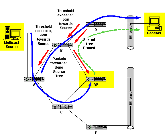
Well, now we’ve got the packets going from the Source to the RP along the Source Tree (Shortest Path Tree, SPT), and from the RP to the receiver along the Shared Tree. When the aggregate (*, G) packet bit rate (from all sources) exceeds a threshold in Kbps, this triggers the router nearest the receiver to try to join the Source Tree. It sends a Join towards the source of the multicast flow. Note that the prior Join it sent was towards the RP. The Join towards the source goes router by router towards the Source until it encounters a router that is already in the Source Tree. This adds the router near the receiver to the Source Tree. When a packet is actually received along that tree, a Prune is sent towards the RP. In effect, “thanks, but I’m now getting my multicast wholesale, not retail”, since this process cuts out the RP in the middle.
The following figure shows how this works. The top left red arrows show the Join towards the Source. This gets the top blue flow going, packets being forwarded along the Source Tree. The lower right red arrows then are the Prunes, since the Shared Tree flow is no longer needed (shown as green dashed line). Note that the Source Tree packets arrive at the Receiver along a more direct path, generally with lower latency.

By the way, we control the threshold. It is configurable. Default is zero Kbps: receive one packet, and switch over to Source Tree. If we have many sources for a particular multicast group (think conference call, VoIP), then there is a (S, G) Source Tree entry for each one. If we set the threshold to never activate, then all packets go through the RP (sort of like a conference calling bridge), using only the (*, G) Shared Tree. The threshold is also used for switchback as well as switchover. Low rate (S, G) Source Trees are switched back over to the Shared Tree. The volume of traffic is checked every minute.
If a receiver wishes to join, and its neighbor router is on the SPT (Source Tree), then the outgoing interface Shared Tree entry is copied to the Source Tree entry, which protects against having to send traffic to the RP and then “back” to the router on the SPT.
By the way, you may be wondering, what is the point of having the RP here? Because of the threshold mechanism, the RP gives us a way to use the Shared Tree, and control the explosive creation of state information in routers if many receivers join at the same time.
Shared Versus Source Trees
PIM Sparse Mode (PIM-SM) can use both Shared Trees (passing through the RP) and Source Trees (for efficient direct delivery along the “shortest” path from source to receiver). Typically, it can use both. If efficient delivery is less important to you, and decreasing the amount of state information kept by the routers is more important, then PIM can be configured to just use a Shared Tree.
When a PIM-SM router receives a multicast packet, it checks the Source Tree for that particular source address and multicast group (destination) address. If there is no entry present, it then checks for a Shared Tree (*, G) entry for the multicast group. If entries are present for both trees, the inbound interface tells the router which tree to use. If both trees have the same inbound interface, then the RP bit for an (S, G) entry prevents duplicate packets: this indicates that the RPF interface lies along the Shared Tree.
For a multicast flow with at least one active receiver, the path between the source and the RP will be part of the Source Tree. (Note that “the path between” is a bit vague here, I’m trying to stay away from giving too much detail.)
Shared Tree entries will connect the RP to some of the receivers. The RPF interface for the (*, G) Shared Tree is the interface in the direction of the RP, not the multicast group source. That why there is the possibility of the (S, G) Source and (*, G) Shared Trees having different RPF interfaces.
The Shared Tree (*, G) entries show interfaces where a join to the RP was received, or interfaces with directly connected group members (configured or IGMP received). The Source Tree (S, G) entries show where a Join or a Prune or a Register was received.
Configuring PIM Sparse Mode
The basic part of what you need is:
ip multicast-routing
interface ethernet 0
ip address 10.1.1.1 255.255.255.0
ip pim sparse-mode
interface ethernet 1
ip address 10.1.2.1 255.255.255.0
ip pim sparse-mode
You also need to tell each router the RP, either for all groups or for selected groups (using access lists to specify which RP for which groups). This can be done statically with:
ip pim rp-address 1.2.3.4
We’ll look at the other options for managing RP in the next article.
In Conclusion
Next month we’ll take a look at the various ways of working with Rendezvous Points. We may also touch lightly on a couple of other more advanced IP multicast topics.
