This is the fifth blog in an Internet Edge series.
Links to prior blogs in the series:
- Internet Edge:Simple Sites
- Internet Edge:Fitting in SD-WAN
- Internet Edge:Things to Not Do (Part 1)
- Internet Edge:Things to Not Do (Part 2)
This blog takes a look at Internet Edge design when you have two data centers.
There are two basic design cases with some key differences: Separate Edge and Shared Edge.
Separate Edge
We start with the diagram showing the “Separate Edge” design:
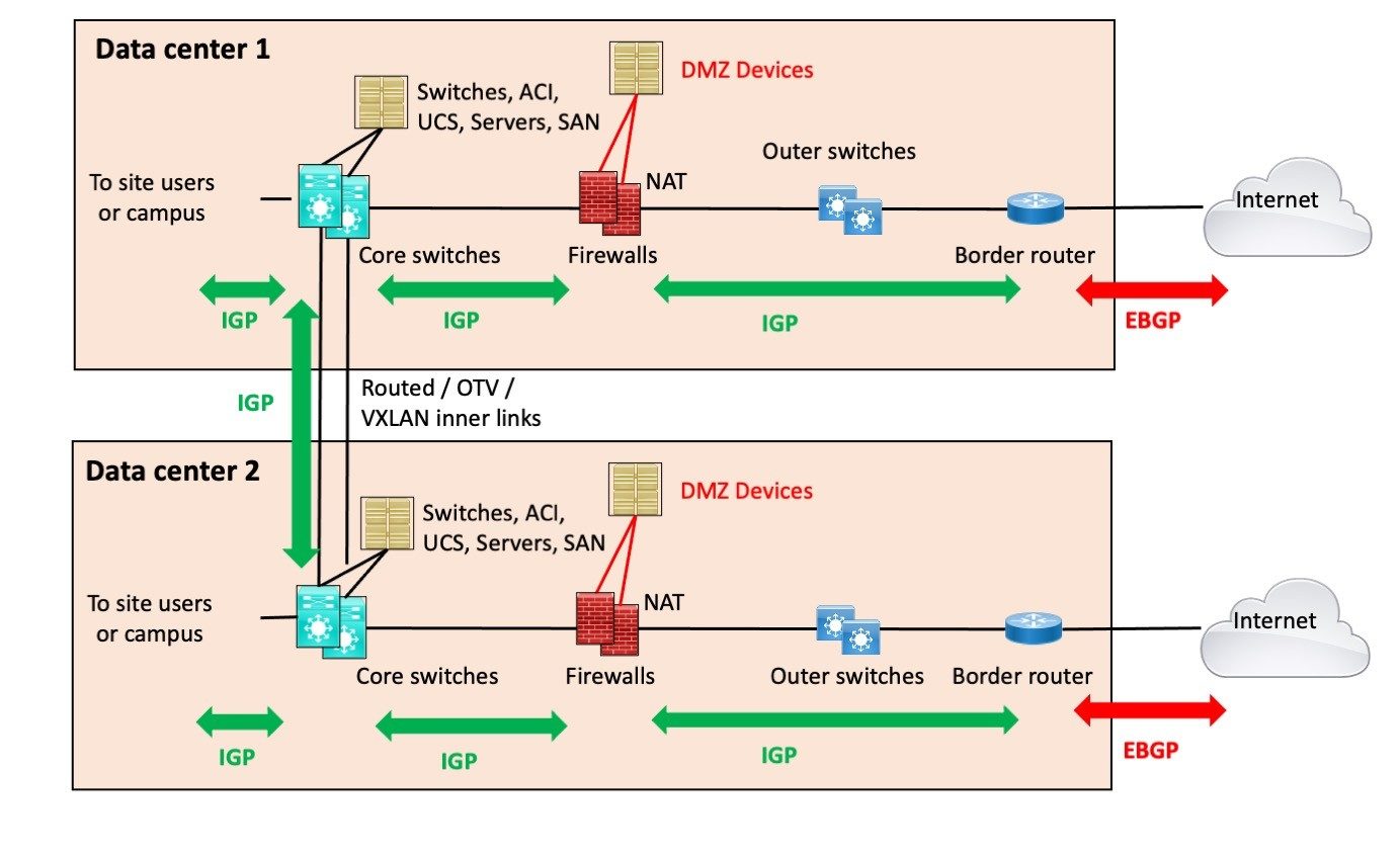 The key point for this design and its name is that the two data centers are joined on the inside by routing (DWDM or fiber, WAN, whatever). But that is the only interconnection.
This is, of course, a perfect world diagram: both data centers identical. In the real world, there are probably a number of differences – but with care, the core components will pretty much look like those in the above diagram.
In addition, I’m assuming the core switches are directly connected to each other, at least a pair of links. That’s the wisest design. More stuff between them, more complexity, and more points of failure
There are consequences to this design choice:
- The main one is that if you’re doing NAT on the firewalls, which most sites are doing, then your failover is unlikely to be hitless. When the edge router or link fails, your TCP sessions will drop, re-route, pick up a different NAT address, and carry on via the other path.
- If your DMZ servers connect via separate firewall interfaces, as shown, you also have to have firewall rules allowing them to exit the other way. That can get complicated. If the firewall they are connected to fails, they would be cut off. That is likely a good argument for having two firewalls at each site.
- If you aren’t doing NAT, you have similar issues, where your BGP has to advertise the DMZ prefixes with AS PATH prepending or some form of “less desirable” out of the other data center site.
- One alternative is to have paired front-end servers for each app, with one in each DMZ. That has the virtue of making the app front end more highly available. The servers could be front-ended on the web by server load balancing. They might or might not maintain state. This can get fairly complex and costs some.
- If you don’t like where this is going, another alternative is to put double links and routers in each data center. This has a cost but may be simpler operationally.
The bottom line here is that the more you try to bullet-proof each component, the more it costs, and usually, there is an increase in complexity. You (and your management) have to decide what the right trade-off is.
Make it too complex, and you not only increase the likelihood of failure but the amount of time you’ll spend scratching your head and saying four-letter words when troubleshooting it.
Shared Edge
One very nice alternative is to have a routed outer link, as shown in the following diagram.

This design is more robust. If either site loses its firewall(s) or router or ISP link, traffic can just shift to the other. As long as the data centers are not too far apart, the latency will not be a problem. (And being down amounts to extremely high latency.)
Note that I’ve skimped on details of how the firewalls and router attach to the two switches in each data center. If the switches operate at L3, those might be routed connections. At Layer 2, maybe port-channels (to a Cisco stack or virtual port-channel Nexus pair?).
The big win with this approach is that with appropriate routing, Internet failover, and so on, NAT sessions can be preserved. Put differently, the traffic from either firewall (or pair) can exit via either ISP, and replies come back in via either one. If the outer link breaks, then you will need symmetric flows out of and back into each data center. NAT or globally routable prefixes for each DMZ helps assure that.
Hybrid Design
There is an alternative if you don’t want to pay for 2 or 4 links between the data centers (perhaps 2 inner and 2 outer).
This alternative does add some complexity.
The following diagram illustrates this alternative approach: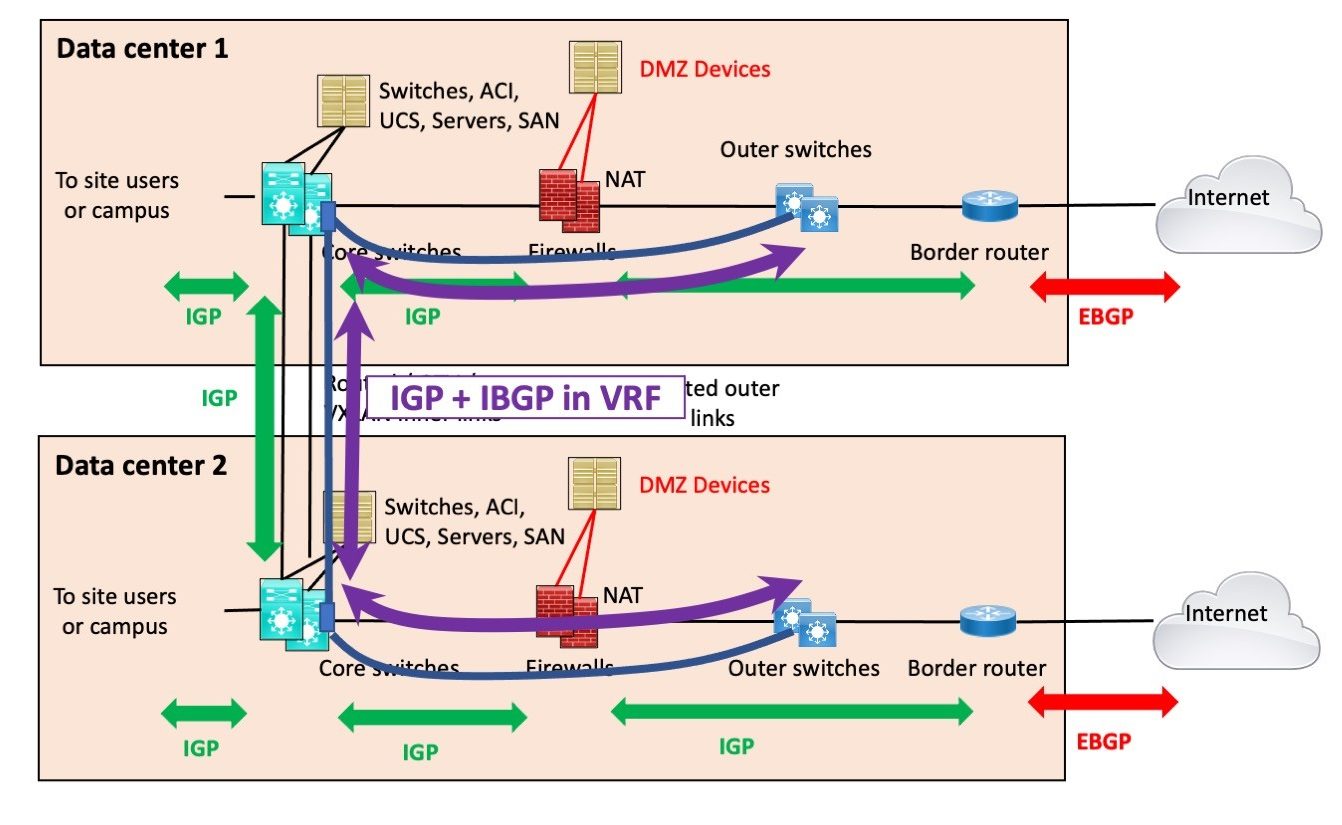
The variation here uses a physical link between the outer switches and the core switches, along with a VRF on the core switches (the purple rectangle at the end of the curved purple arrowed line).
That provides a non-global routed link, a logically separate routed link or links, between the outer switches. We might call this a “virtual outer link.”
That path can then support VRF routing for the IGP between the firewalls and the border routers, as well as IBGP between the border routers.
This solution is mildly more complex but might hold the cost down.
I recall using a variant of this a while back, where another set of VLANs or links plus VRFs could provide a routed cross-link between the DMZ switches. If you had any kind of Ethernet link supporting dot1q subinterfaces, it was usually cheaper to do that than having 2 or 3 separate physical cross-links. Yes, more complex.
L2 cross-links are also possible but, of course bring with them more risk of problems. I trust spanning tree to develop problems.
If you have two inner links, that’s redundant enough. I wouldn’t try extending the VRF any deeper into the campus side of the data center.
Exercise for the Reader
You might, of course, have two border routers and ISP links at each data center, for additional robustness.
Lab Exercise: How would you design that? Sketch the diagram and the routing peerings.
Conclusion
There are of course many variations on the basic approaches shown above, so your site may well differ from the diagrams. That’s OK!
I do hope this blog provided some food for thought, and / or will be helpful in your next design, or for improving your current design. I’ll also note that I’ve stayed fairly high level, so you may have to adjust some of the details, depending on your particular circumstances.