This blog is about how to secure traffic coming from the SD-Access fabrics, emphasizing SD-Access Transit designs.
Prior blogs in this series:
The starting point for this blog is the assumption that you want to review the routing alternatives for traffic between sites and how to deploy a fusion firewall (“FFW”) controlling traffic between your SDA VN’s (VRF’s) and/or also between users/devices and the datacenter. Or you want to read about how a fusion firewall might work.
Design Alternatives
There are two alternative designs to cover:
- Non-segmented Backbone: IP Transit where your border node (BN) to backbone handoff ties fabric site VN’s into the global routing table. Doing this gives up the ability to control VN to VN traffic between different VN’s. With SXP or equivalent approaches to the firewall, you would use SGT’s to control who can access what in the datacenter. You might also deploy firewalls instead of a fusion router to connect the site BN’s to the core network, but that does not scale well to many sites (labor, firewall purchase costs, etc.)
- Segmented Backbone: IP Transit with VRF’s across the backbone, or SDA Transit. Either of these choices preserves the separation between VN’s/VRF’s and allows the use of a fusion firewall to control inter-VN (VN to VN) traffic, as well as all user/device to datacenter traffic. If you have datacenter VRF’s, they might also be tied into the fusion firewall.
There is little to be said about the first of these, non-segmented designs. You either route sites into the global routing table, carry them in the core or WAN without segmentation and possibly use SXP at some edge firewall.
The routing is straight-forward, and everything would be pretty much like what you were doing before SD-Access. Recall that SXP maps IP to security / scalable group tag (SGT) and is available when using ISE 802.1x / NAC without SD-Access.
An alternative, which falls under the “Segmented Backbone” case, is to create VRF’s across your core and carry segmentation to the edge or datacenter firewalls. If you do that, much of what is below about fusion firewalls might apply to your data center firewalls.
Note: Manually creating VRF’s and per-VRF routing adjacencies across a core or WAN network can be done. It takes a lot of work. This also applies when you add a new VRF. The same applies to plumbing VLANs for segmentation across a core, perhaps with a routed hop in a VRF at site boundaries. It can be done, but it’s a lot of work. And with VLANs, there’s L2 stability risk. If SD-Transit tunnels concern you, manual plumbing is an option. Read on…
The rest of this blog will discuss the Segmented Backbone/fusion firewall case.
About VXLAN Tunnels in SDA
One pleasant aspect of SD-Access is that we auto-magically get traffic in LISP-based VXLAN tunnels with the SGT as part of the VXLAN header. This saves us from having to configure TrustSec on fabric links – I don’t think anybody thought that was particularly fun.
Since SD-Transit uses automatic VXLAN tunnels between sites or to the datacenter, we get the same benefit there. Compared to configuring VRF’s all over the core, that could be a big win!
An SGT Surprise
One early surprise to me was that DNAC does not configure inline SGT tagging from border nodes to the fusion firewalls. The consequence is that we have to rely on SXP or pxGrid to map IP to SGT, so the firewall knows the SG the traffic is sourced from.
The good news is that this approach does make it easier to use non-Cisco firewalls, as long as they have an intermediary that handles SXP or provides equivalent functionality. (See also the first blog in this series.)
VRF Rainbow to Fusion Firewall
SDA expects us to connect the border nodes to the fusion firewall using BGP routing and with VLANs on trunk interfaces (dot1q subinterfaces from the firewall perspective). DNAC will pre-configure the switch BGP, the trunk, the VLANs, and the VLAN IP addresses on the border node(s).
Users are expected to manually configure IBGP between the pair of BN’s. (Maybe they’ll automate that in an upcoming release.)
Users will also have to configure dot1q sub-interfaces on the firewalls, addressing, and BGP to match the pre-assigned addresses on the BN’s.
If you don’t like this, you’re welcome to do it your way. Doing so may or may not co-exist with DNAC cleanly – I have not experimented with that in the lab. Co-exist in the sense of not making DNAC complain or not getting over-written by DNAC.
The BGP routing ties each VN/VRF on the BN’s to the global routing instance on the fusion firewall. That means the fusion firewall acts as a “mixing bowl” for all the traffic through the firewall, either between VN’s/VRF’s or from a VN to the datacenter or Internet.
Here’s what that looks like:
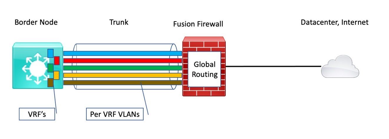
This is why I’ve started referring to the connection as a “VRF rainbow.”
Note that the above diagram is simplified. For high availability, we would have two BN’s and two fusion firewalls (“FFW’s”). We’d probably like to have a port-channel from each BN to each FFW or one VPC port-channel from the BN’s to the FFW’s.
But that’s not what DNAC apparently expects.
Lesson Learned: The DNAC -provided configuration sets up independent and different VLANs on the BN’s. And you cannot over-ride that! That means you cannot port-channel to the FFW. Not that the Catalysts do port-channel like Nexus VPC’s from two separate devices. (And I really would prefer to not stack my BN’s – shared fate.)
Instead, you end up with BGP and two different routed interfaces to the FFW (one VLAN per BN using different subnets and IP’s).
If asymmetric routing is a problem, as we found it to be in the lab with an FTD, you either need to bias the routing to prefer one of the links in- and out-bound to the FFW, or you need to configure ASA style zones. We found that doing the latter breaks IP multicast.
A third option is to insert an L3 switch pair in the middle. I tested this with a single switch in the lab: route the two BN VLANs per VRF into the switch then out a single link / single VLAN per VRF to the FFW. It worked. It gets complicated.
It might be better to put a Nexus pair doing VPC in the middle. Route from each BN to one of the Nexus switches on a routed port. Route out on a VLAN over a VPC port-channel from the pair to the FFW. I haven’t tried that but strongly suspect it would work.
You could even do that with an adjacent datacenter switch pair, although that makes the logical topology complex. In terms of the diagram below, imagine bending the VRF rainbow so that it goes from BN to FFW via the adjacent switch pair. That’s actually how I lab tested it without having to change my cabling, single switch style in the lab.
I don’t advise doing that. Supporting it would be rather confusing. The issue: SD-Transit tunnel traffic crosses links to the BN one way in a global context, then gets routed over a VRF / VLAN back to the inner routers and from there to the FFW. The FFW then routes it back to the inside routers in a global context if it is headed for the Internet or the datacenter.
(If you can follow that without a diagram, then maybe you’re up to the inherent complexity in that approach. Challenge for the reader!)
The Routing Big Picture
The next thing to consider is how the routing should work, in terms of tying into the routing into and out of the data center, etc.
For SDA Transit, I will admit, at first, I needed to draw a diagram to confirm how things work. In fact, to convince me, the routing could work.
Here’s how I think about the SDA Transit FFW routing, diagrammed in terms of packet forwarding logic. (If you’re thinking in terms of who advertises what in routing updates, this is the reverse of that.)
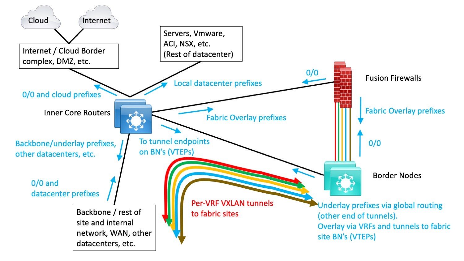
There will be on-demand per-VRF per-fabric site LISP-based VXLAN tunnels from fabric sites to the datacenter border nodes. Those would be extended with per-VRF VLANs / dot1q sub-interfaces to the FFW pair. The colored lines in the above diagram are intended to suggest this.
For IP Transit with VRF’s carried across the backbone network, this is what the result might look like:
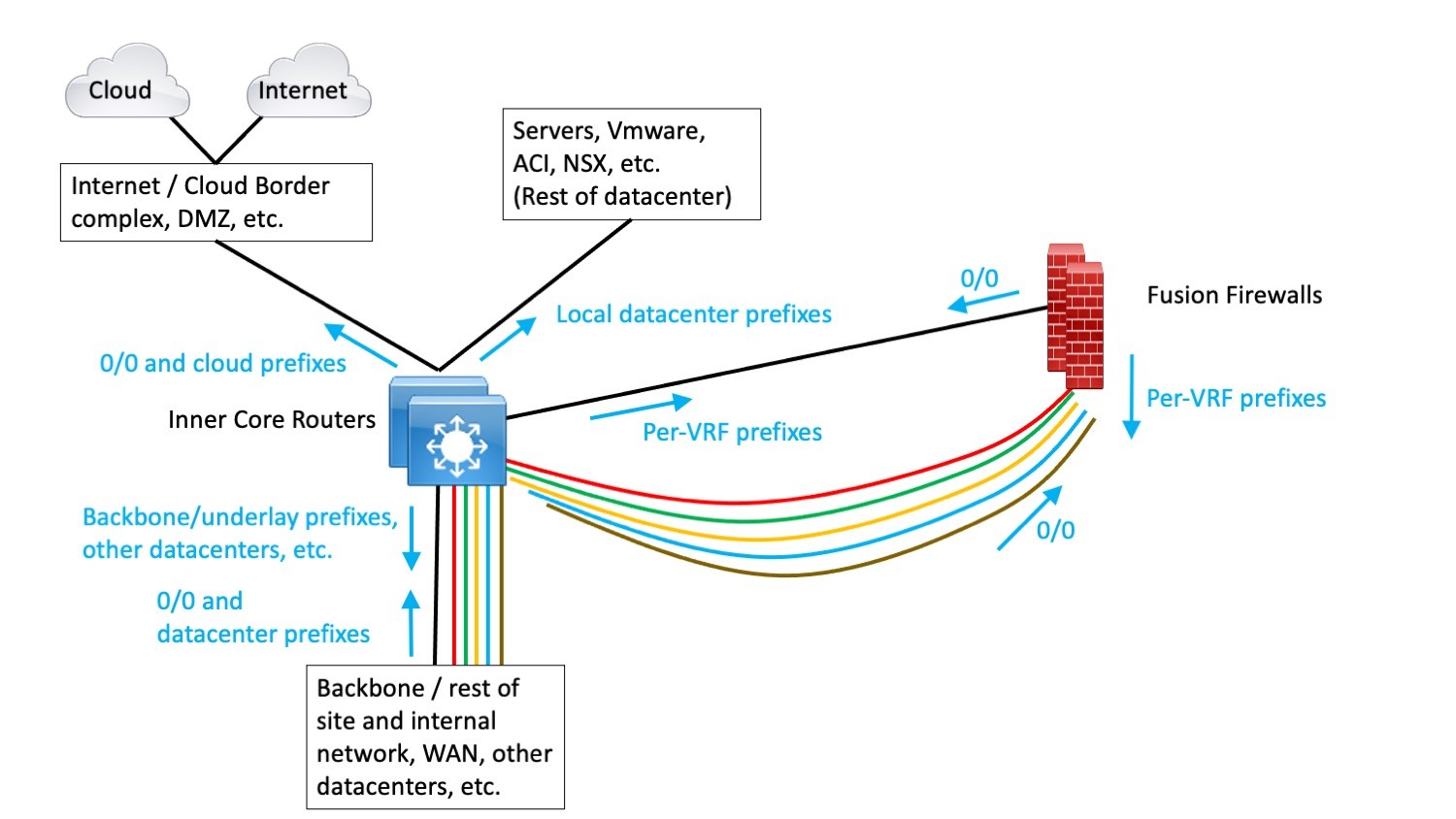
(No tunnels, just VRF’s and subinterfaces.)
In the above diagram, black links are in the global routing context. The SDA VN’s mate up with VRF’s in the backbone, represented by the colored lines in the diagram. The only exit from any VRF is via the FFW’s, following the default route, 0/0.
By this means, user/device traffic from the SDA fabrics is carried in segmented form over to the FFW. From there, traffic that is allowed can flow between SDA VN’s and to/from the data center, cloud, Internet, or other parts of the network via the global routing table.
Note that with both of the above, some VLANs or VRF’s might be connected to a second FFW to split and reduce the traffic load. Doing so increases complexity and management effort, and if not done carefully, may not help much with scaling. Buying lots of firewalls might make your salesperson happy. It probably will not make you happy. We leave the details to the reader as a homework exercise.
What to Filter Where
Overall security design also needs to consider which security controls go where. And, of course, document the design (an often-overlooked step).
For users and devices connected to SDA devices, SG to SG (same VN) traffic should be controlled right there, using the SDA policy configured via DNAC. The fusion firewall (FFW) is closer to the servers, so it may be a more appropriate place to define and use groups of servers for policy. In particular, it is a great place to impose a group-based user/device to server, cloud, and Internet controls.
Having the FFW also makes it a single monitoring point that sees all of the user/device traffic to servers, clouds, and the Internet. It does not see fabric to fabric the same-VN traffic, but the SDA devices can report on those flows if desired.
If ACI is present, the author likes keeping it separate, at “arms’ length,” so to speak, as better modularity.
To save money, ACI might be used for policy enforcement instead of using a (large!) FFW. Doing so would be less clean modularity – separation of functionality. But ACI can be integrated with SDA, mapping SG’s to EPG’s, creating counterparts where absent, and using SXP to map IP to SG to EPG. Of course, ACI does not provide the IPS type features that a next-gen firewall does. Maybe your border firewall does that (lower speeds there, so costs less.)
For virtualized server / application-oriented controls, if NSX is present, most sites do the controls there since traffic may not be visible outside NSX. For physical servers’ traffic, ACI is a good place to control that, if present (typically also with VMware ESXi rather than NSX).
References
Cisco Press book, Software-Defined Access
I don’t know of any good references on this specific topic. The Cisco documents cover some of the mechanics of deploying an FFW, but part of the goal above was more the big picture, especially the non-SDA-Transit “VRF rainbow” across the core possibility.