This is the eighth blog in an Internet Edge series.
Links to prior blogs in the series:
- Internet Edge:Simple Sites
- Internet Edge:Fitting in SD-WAN
- Internet Edge:Things to Not Do (Part 1)
- Internet Edge: Things to Not Do (Part 2)
- Internet Edge: Double Data Centers
- Internet Edge: Double Don’t Do This
- Internet Edge: Cloudy Internet Edge
This blog in the Internet Edge series will examine some special cases. As a special treat, I’m going to start by critically reviewing my own advice!
CoLo Portal Design
The prior blog suggested a low-device-count solution for a CoLo with a Portal (PacketFabric, Equinix ECX, Megaport, etc.).
As Russ White constantly says: “What are the trade-offs?”
Here’s the diagram again:
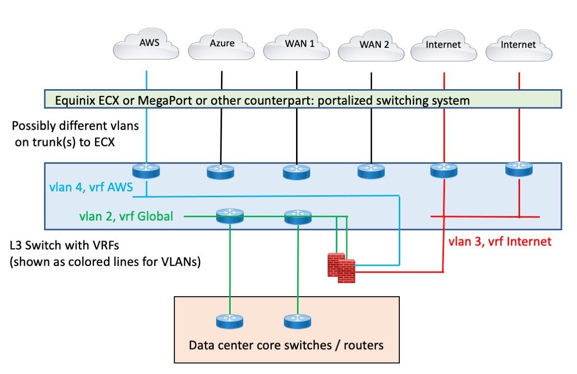 Figure 1: Leveraging CoLo Portal for Connectivity
The positive aspect of this is you are using something like a Cisco Nexus 9000 switch instead of a pile of routers. Doing so takes up less space.
The negative aspect is that you’ve virtualized the cabling and the devices, which inherently is a bit more complex.
On the other hand, the portal-based “automated WAN switching system” (for lack of a better term) is the CoLo provider’s virtualization. Using an L3 switch means you can virtualize physical links as VLANs on a trunk to use the automated WAN switching system as it is intended to be used.
Why L3 switch? You could probably do this at L2 with the routing on the firewall, which is likely doing routing anyway. I prefer L3 for this so as to have IP addresses on the switch and be able to do ping etc., or packet inspection if there are connectivity problems. For example, some CSPs do single VLAN tags, some do double tagging or give you a choice. Being able to see what they are sending is key to fixing initial connectivity problems.
Data center Spaghetti
Visibility is darn important for troubleshooting and maintaining a data center.
There’s a tendency with VMware (etc.) to have one big server farm, serving up VMs for both internal server functions and DMZ server functions. Rather than having a separate VMware cluster, etc., for the DMZ, with higher cost (licenses, admin, etc.) and less flexibility about allocating resources across both internal and DMZ functions.
However, it may be helpful to think of VMware and design so it is logically separate groupings of VLANs. If you can conceptually partition what’s in it, that can help with understanding. It may also help with ACI.
Having all of VMware connected via a pair of ACI leaf switches and doing ACI contracts can lead to TCAM overload. But I digress. VMware, monolithic “server farm”, now let’s get to the story.
I’m now going to share a story, blending a real-world site and some fiction.
The fiction is needed because I never did get a usable diagram or explanation of what the real-world site had built. The following represents what I think was going on.
The data center core switches are connected to a large number of data center switches, chassis blade switches, etc. (Large = 90+ mostly small switches, stacks, etc., with data center-wide VLANs.)
There were a number of server VLANs. Also, there were perhaps 8 DMZ VLANs for segmented external exposure. Deep in a monolithic data center combining old/new/virtual servers. Those 8 separate VLANs and the other server VLANs crossed multiple switches up to the data center core. They were then trunked to the DMZ core switch pair.
The data center core switches also served as campus cores, so they also had several user/guest VLANs on them, spanning 3-4 buildings.
So far, not too bad, although a diagram would have helped.
I gather the server DMZ VLANs then fed them into multiple firewall pairs. I think the firewalls operated at L2, stitching the inside VLAN to a different shared outside VLAN, times 8.
The outside VLAN(s) then went back through the data center core to get to the WAN / Internet core switches.
Here’s my attempt to draw this, based on poor recollection and never having decoded the connectivity (not the main purpose of the work I was doing).
Figure 2: Diagram of Data Center / Edge Complexity
Did you notice that a diagram helps a lot?
The green and red trunk links would have carried, say, 8 VLANs each, at least.
I’m impressed! My diagram makes it all (potentially) a lot clearer. If I’d had such a diagram at the time, I might have deciphered more of the connectivity!
In actuality, the design may have been more complicated. I’m deliberately not going back to my notes to check – this story is already long enough!
Issues with this:
- L2 firewalls are pretty much invisible when tracing connections. Having IP and MAC addresses helps with that if you’re trying to avoid cable tracing. Good cabling documentation/diagrams are worth a LOT! I prefer L3 firewalls myself. While they may not be as “stealthy” or whatever, they’re operationally more manageable.
- The DMZ switches may have been vestigial, i.e., formerly used by directly attached servers pre-VMware. They may also have been there due to the multiple firewall pairs, perhaps with different admins.
- Passing DMZ VLANs to the DMZ switches and doing the firewall plumbing there could still make sense. Passing the ‘outside’ VLAN(s) back through the data center core, maybe not.
- The problem was partly that the big data center core switches were also the DMZ switches AND the campus cores for all the closets, AND were effectively the WAN core for a bunch of WAN and Internet routers. If there were a separate WAN core, then passing DMZ server VLANs to the DMZ switches and from there to the WAN core would make a lot of sense. And having the DMZ switches be the only way to get to the WAN from the data center core might also have been a good idea for greater consistency (predictability) of paths.
- No diagrams! (Job security for the security team? Or “limiting distribution of sensitive information”?)
- There were a lot of other edge devices in the path from the data center core to the Internet routers. WAN accelerators, web proxies, etc. They added complexity but don’t really add to the point I’m (slowly) making here.
- Lack of modularity. I prefer a clean separation of a data center, edge / WAN, and campus/user modules. E.g., different core switches for each.
- I’d have put the DMZ switches and firewalls in closer proximity to the Internet. However, they may have also been filtering traffic to the WAN or cloud. (More complexity if non-DMZ VLANs feed into and out of the firewalls.)
So, what’s the point of this story?
Key question: How did anybody ever audit the security, given the lack of diagrams and information?
Conclusions: VLANs winding through various devices become complex. L2 stitching of pairs of VLANs by an L2 firewall adds complexity. Lack of modularity adds complexity.
So, build with modular design, and create summary diagrams – they don’t have to show every detail. Supplement the diagram with tables or something indicating which VLANs connect where and their purpose.
Security by obscurity is not your friend when troubleshooting. Or when evaluating a design for security gaps.
Exercise for the reader: How would YOU design this?
Spaghetti Reheated
There might be another aspect to the prior design, one worth mentioning.
I’ve seen organizations with separate firewall pairs dedicated to functions like WAN, CSP, Internet. That, to some extent, distributes the firewall rules. However, it can also mean that some rules have to be put in two places to control traffic coming in a WAN router and out a CSP router, etc. Having separate firewalls adds purchasing cost and staff admin time/cost.
The extreme case of this is where you have many “security enclaves” each front-ended with a firewall pair. Imagine the labor/maintenance burden of 20 or 30 such enclaves!
So centralizing firewall functions into one firewall pair can make sense. In that case, I’d probably connect the firewall pair directly to the WAN / Internet edge module core switches, assuming a modular design.
Service Chaining and Spaghetti
ACI and the Cisco SD-WAN routers can do service chaining, redirecting traffic elsewhere. It is similar in a way to Policy Based Routing (PBR): take traffic between A and B on ports C etc., and especially forward it to somewhere (firewall).
I have yet to encounter this in the field, which may be just as well.
Service chaining seems like it could be darn useful. But it better be designed in an organized way, with good naming and documentation, or else troubleshooting it will become a nightmare. The “good documentation” part is what I very rarely have seen in years of doing networking.
More specifically, think of it as PBR-like rules applying across your ACI fabric or different parts of your SD-WAN, forwarding traffic to e.g., a firewall. This topic is a bit tangential to Internet Edge, so I’m not going to elaborate on it further here. I included it because it seems somewhat similar to the prior section.
For What It’s Worth: I’ve just been reading Arista documentation. It looks like their MSS selectively forwards traffic from edge switches to firewalls based on policy. This is another form of service chaining, in this case to provide data center macro-segmentation. It appears somewhat similar to what Cisco SD-Access Transit ends up doing with a fusion firewall, except the VXLAN apparently terminates on the switch adjacent to the relevant firewall. And how different is it from what Cisco ACI service chaining does?
My answer for now: do it consistently to some pattern, and document it well!
But VPN?
Most sites put their site-to-site VPN firewalls or other VPN termination devices and remote access devices in parallel with the Internet firewalls. Or inside them, if required or deemed useful.
I haven’t included them in the discussion since (like many security edge devices); they are pretty much just an add-on.
Conclusion
The overall lesson learned is to plan ahead when adding to the edge. A good design will scale well. A poor design will get uglier as more is added to it. Think maintainability!
And do document the connectivity and intent, how “it” is supposed to work. And keep the documentation up to date – which means NOT overdoing it to the point where it is too much work to maintain. Overly elaborate diagrams with a lot of information packed in are hard to maintain. Device names, interfaces, and IP addresses are as far as I’m willing to go when diagramming.
Hint: Use a spreadsheet for any other information, cabling details, whatever!
So “think maintainability” also applies to documentation and diagrams.