This blog is part of a series covering various SD-Access topics.
Previous blogs in this series:
- What Is SD-Access and Why Do I Care?
- Navigating Around SD-Access
- Managing SD-Access Segmentation
- Securing SD-Access Traffic
- SD-Access Single-Site Design
- SD-Access Multi-Site Design
- SD-Access Multi-Site Lab
- SD-Access Multi-Site Lab Tasks
- SD-Access IP Pools
- SD-Access and e911 Services
- Migration to SD-Access
- SD-Access and Wireless
- SD-Access Study Resources
- SD-Access and Internet of Things
- SD-Access: SD-Access Flows: Registration and Same Fabric Forwarding
The previous blog covered the registration, LISP, and traffic flows for the same fabric site forwarding.
This blog covers multi-site, where you are using IP Transit. As a special case, we discuss how routing between VNs works in an IP Transit setting (depending on your design, of course).
This blog also covers another noteworthy situation, where you have a site with mixed BNs, one that is an “Anywhere” BN (internal + external) and one that is just an internal BN.
Please look at the referenced CiscoLive presentations if you wish to supplement the amount of detail below.
Context
The context for this blog is a multiple SD-Access fabric site, using IP Transit to connect them to each other.
Cross-Site Forwarding with IP Transit
When Host A needs to send to Host B that is at another site, SD-Access handles that as follows.
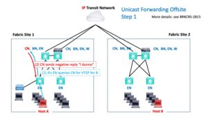
As usual (by now), the VTEP EN that A connects to queries the CN for the VTEP associated with the destination IP. The CN responds with a negative reply: “it isn’t local.” Because of that, the packet is forwarded to the BN, which handles routing-based forwarding.
The BN then routes the packet out into the IP Transit network.
There are two possibilities (cases). Either:
- The transit network is doing global routing table (“GRT”) only.
or
- The transit network carries all / most VRFs to all connected sites. (I’ve been calling this a “VRF rainbow” since every time I draw it, it looks like a bunch of colored lines in parallel.)
Let’s look at these two cases one at a time.
Case 1: Transit is GRT Only
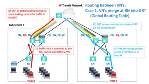
If the transit network is GRT only, your VRF at the BN has to tie into that somehow. I personally try to always do “route leaking via cable,” where one end of a cable or dot1q subinterface thinks it has a VRF, and the other end thinks it is globally routed.
Configured route leaking is the other choice. I personally try to avoid that as added complexity and configuration. Yes, if you’re route leaking by cable, you’d better document it well!
So our packet enters the transit network and uses global routing to get to the destination BN.
The following diagram shows this. The fading colored lines are intended to suggest the VRF to GRT merging.
Case 2: Transit Has VRFs Throughout
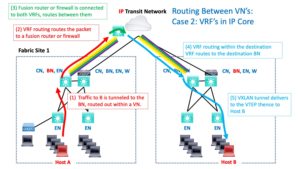
For the second case, you’re routing within a VRF. If the destination is in another VN / VRF, something (fusion router or firewall) has to provide routing between the VRFs.
(Bad dad joke: when you do something with fusion routing, does that lead to “con-fusion routing”?)
The following diagram shows this. The fusion device has some interfaces in the source VRF (red arrow) and some in the destination VRF (light blue arrow). It routes between them (green curved arrow in the middle). The multiple SOLID colored lines are intended to suggest that the VRFs extend across the transit core (rather than sort of fading out / becoming less relevant since merged with the GRT).
Completing the Journey
So routing gets the packet into the destination VRF and over to the BN at the destination site.
The destination site BN queries the CN if necessary (if the destination to VTEP is not mapped in cache already). And then, VXLAN tunnels the traffic to the destination switch (EN). The switch de-encapsulates the packet and forwards the packet natively out the port to Host B.
Return traffic works similarly.
Internet Routing
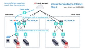
If traffic is headed for the Internet, presumably, your transit network’s global routing routes it there and routes it back. The return path is essentially the reverse of the outbound path. The device that routed from the VRF to the GRT may well do the reverse routing. (Ignoring any details of HA pairs of devices.)
That’s shown in the next diagram. Some device somewhere has to get the traffic from the VRF into the GRT. That might happen due to the way the BN connects to the transit network (“route leaking by cable”). Or there is some device in the path with some interface(s) in the VRF, some interface(s) in the GRT, routing between them (“fusion”).
Unicast forwarding to another non-SDA site works similarly.
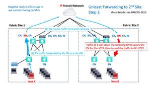
In the first case, VRF to GRT leaking, the packet gets forwarded via the GRT. Then GRT to destination VRF leaking/routing happens and gets the packet into the destination VRF and to the destination site BN. Which then tunnels the traffic to the destination Host B in the usual SD-Access VXLAN fashion.
In the second case, “rainbow VRFs,” there has to be a fusion device somewhere that is connected to both VRFs and routes between them.
The story, either way, is that routing gets the packet from Site 1’s BN to Site 2’s BN. The details are what differs in the two cases.
Once the destination BN receives the packet, it does a destination lookup with the CN if the info is not cached, and then VXLAN tunnels the traffic to the destination EN, which de-encapsulates the packet, and forwards it out to the correct port.
Care with Diverse BNs
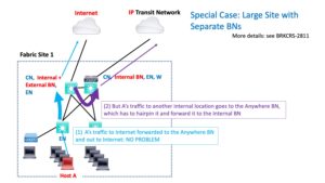
There is one situation that can arise if you’re not aware of it. It happens when you mix “anywhere” (internal + external) BNs with internal-only VNs. In general, the principle is to use external for Internet or outside entities, and internal for routing to other sites, data centers, etc. within the organization.
Generally, with SDA, sites need to only be aware of their own prefixes. The BNs take care of routing to other prefixes.
If you have an external + internal (anywhere) BN, it is initially used for all forwarding to other locations. If the destination is external / Internet, no problem, that’s what you want. But for internal locations, it may have to forward to another internal-only BN that has the IP transit link. See the purple arrow in the diagram below.
The conclusion is that when you design a site, the internal BNs should be ones that actually connect directly to the transit network and to the other internal sites.
You can have anywhere BNs as long as they all can forward directly to the internal transit network. This is fine for smaller sites.
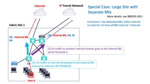
For larger sites, where you’re splitting the responsibility, the BNs should be external only if they do not connect internally.
The following diagram shows the optimal design that avoids the extra hop shown above:
In this diagram, external traffic goes to the external BN, internal traffic goes to the internal BN, and there’s no unnecessary extra hop.
References
- Cisco SD-Access Technology Deep Dive – DGTL-BRKCRS-3810
- Cisco SD-Access for Distributed Campus – DGTL-BRKCRS-2815
- Cisco SD-Access – Connecting the Fabric to External Networks – BRKCRS-2811

